News Crimping Might Have Prevented RTX 4090 Adapter Meltdown: Report

nimbulan

Distinguished
Apr 12, 2016
37
32
18,560
Except as others have noted, the connectors are melting at the end, not where the solder joints are. This suggests that the solder joints are not where the excessive heat is being produced. The most promising theory I've seen is that the barrel connectors inside nVidia's power adapter plug are split along both the top and bottom so there's no structural support horizontally, allowing them to easily loosen up, resulting in poor electrical contact.
 
  • Like
Reactions: Soaptrail

InvalidError

Titan
Moderator
I doubt soldering had anything to do with the failures. Crimping onto something that is only 0.2mm thick would likely be every bit as problematic structure-wise. And then you have Igor's piece saying it the split terminals may be the root cause since there is almost no structural integrity keeping the terminals from becoming loose, which crimping would do absolutely nothing about.
 

BillyBuerger

Reputable
Jan 12, 2021
168
87
4,660
Except as others have noted, the connectors are melting at the end, not where the solder joints are. This suggests that the solder joints are not where the excessive heat is being produced. The most promising theory I've seen is that the barrel connectors inside nVidia's power adapter plug are split along both the top and bottom so there's no structural support horizontally, allowing them to easily loosen up, resulting in poor electrical contact.
The connectors are melting because some solder connections are failing putting more current through the ones that didn't fail which then causes those connectors to overheat and melt. So the issue is the soldered connection that then causes the failure in the connectors.

As someone who also likes to dabble in car audio with very thick power wires, I've seen plenty of debates on solder versus crimping. The overall consensus seems to be in favor of crimping. Solder on wires that move or vibrate can fail over time as solder is brittle. A good crimp job can hold very well as it creates pressure holding the wires together instead of the solder itself holding the wires. Not to say a bad crimp couldn't cause these same issues. So either way, the QC of these things failed big time.
 

Kamen Rider Blade

Distinguished
Dec 2, 2013
1,280
810
20,060
I doubt soldering had anything to do with the failures. Crimping onto something that is only 0.2mm thick would likely be every bit as problematic structure-wise. And then you have Igor's piece saying it the split terminals may be the root cause since there is almost no structural integrity keeping the terminals from becoming loose, which crimping would do absolutely nothing about.
The Double-Split terminal analysis was from Buildzoid of AHOC.

But I don't understand how much money was nVIDIA saving by going with 4x 14-AWG copper wires in the adapter over 6x 16-AWG copper wires that other vendors would use?

Anybody care to guess what the BOM cost difference would be?

How much would 6x crimped 15-AWG copper wires cost?

I would prefer "Crimped" wires as well and a fundamentally different design than what nVIDIA contracted out to "Astron".

Imagine, instead of 4x seperate 4" cables to 4x 6+2 PCIe Power Receptacles that look like squid tentacles.

How about a Isoceles Pentagonal or Hexagonal PCB that mountes the 4x 6+2 PCIe Power Receptacles & a Aluminium or Plastic housing to protect the PCB.

Then route the power through the PCB & logic chip that nVIDIA used, then through a longer set of proper 6x 15-AWG copper wire pairs w/4 sense wires to the PCB that are properly crimped and strain relieved.

How much longer, say somewhere between 12" & 18" so users can route the adapter to somewhere behind the PC case.

How much more would that have cost to build?
 
Last edited:

InvalidError

Titan
Moderator
But I don't understand how much money was nVIDIA saving by going with 4x 14-AWG copper wires in the adapter over 6x 16-AWG copper wires that other vendors would use?
The reason for 4x#14 for 12V and ground likely had more to do with there being four 8-pins connectors to aggregate into one. If you wanted 2x ground + 2x 12V from each connector going to the GPU, then you'd have to somehow attach 16x #16 to that thing.

Then route the power through the PCB, then through a longer set of proper 6x 15-AWG copper wire pairs w/4 sense wires to the PCB that are properly crimped and strain relieved.
No need for a PCB, just solder all terminals to a single #10 wire to aggregate the 4x6/8-pins, then you only need 2x#10 going to the GPU connector.
 

Kamen Rider Blade

Distinguished
Dec 2, 2013
1,280
810
20,060
The reason for 4x#14 for 12V and ground likely had more to do with there being four 8-pins connectors to aggregate into one. If you wanted 2x ground + 2x 12V from each connector going to the GPU, then you'd have to somehow attach 16x #16 to that thing.
IC

No need for a PCB, just solder all terminals to a single #10 wire to aggregate the 4x6/8-pins, then you only need 2x#10 going to the GPU connector.
I'd rather not have a "Squid" like appendage with extra wires dangling.

That's why I prefer the Pentagonal or Hexagonal PCB box solution with a single set of wires routed from the box to the 12VHPWR plug.
 

wmeyer

Distinguished
May 21, 2009
5
1
18,515
There really is no mystery over which method is better: Solder is only meant to stabilize a mechanically secured connection. Solder is soft; depending on it as a mechanical means of attachment is folly.
 

jasonf2

Distinguished
High amperage connection and solder are a bad mix. One of the issues not noted here is the fact that solder has a relatively low melting point. When a solder joint goes hot it has the potential to melt itself and come apart. It is for that reason that soldered joints are all but illegal by code in high voltage systems. (Yes there are a couple of exceptions, but they are related to factory production applications, not field connections). They used to do this back in the knob and spool days and it caused house fires. When you take into consideration the crazy combined wattage on this connector is more than most soldering irons there is no real surprise that things are coming apart. If my rough math is right at 400 watts / 12VDC you have about 33 amps spread across the connectors. You need an RV power connector not a 16 pin connector. Lol
 

InvalidError

Titan
Moderator
High amperage connection and solder are a bad mix. One of the issues not noted here is the fact that solder has a relatively low melting point.
Low? Lead-free solder melts at 235C. The connector and PVC wire insulation will be a smouldering mess long before the solder's melting point becomes a concern. The "low" melting point of lead-free solder is only a problem when your application is expected to hit 200+C under normal operating conditions.
 
  • Like
Reactions: thisisaname

PlaneInTheSky

Commendable
BANNED
Oct 3, 2022
556
759
1,760
On other applicances using similar amount of power, there are big warning signs on the back that tell you to never open these devices if you're not a qualified electrician.

Meanwhile, 15-year-old kids will soon be tinkering with the connections of a 450 watt GPU. This will not end well.
 

Amdlova

Distinguished
Tre problem is the connector, not the solder, less contact pins with more pins are bad... the resistance over the pins make the power run over less resistance and the pin will melt it self. On the old connector the problem is the thick of the cable not the connector it self. This new connector have less thick cables and more cables with variable ohms rate.
 

InvalidError

Titan
Moderator
On other applicances using similar amount of power, there are big warning signs on the back that tell you to never open these devices if you're not a qualified electrician.
The shock hazard warning is due to the voltage, not wattage. You don't see those warning on a ICE vehicles despite the alternator being able to deliver 1200+W and the battery being able to deliver 3000+W peak at 12V.
 

InvalidError

Titan
Moderator
This new connector have less thick cables and more cables with variable ohms rate.
The old connector had 3x #18 cables, the new connector has 6x #16 cables. It has HEAVIER wire gauge, not thinner. The wiring resistance from wire to wire is pretty much exactly the same between same-length same-alloy wires. Practically all of the "variance in ohms rate" comes from the connector.
 

Amdlova

Distinguished
The old connector had 3x #18 cables, the new connector has 6x #16 cables. It has HEAVIER wire gauge, not thinner. The wiring resistance from wire to wire is pretty much exactly the same between same-length same-alloy wires. Practically all of the "variance in ohms rate" comes from the connector.


The old connector has 3 #18 cable for 150w, the new model has 6x 16#... How the 12 cables with 20 ground cables can be worst? Have more cooper to dissipate the heat, less prone have failure on ground. The only thing the new connector have is increase profit over the user.
 

InvalidError

Titan
Moderator
The old connector has 3 #18 cable for 150w, the new model has 6x 16#... How the 12 cables with 20 ground cables can be worst? Have more cooper to dissipate the heat, less prone have failure on ground. The only thing the new connector have is increase profit over the user.
The ground pins and wires don't matter much since the PCIe slot is mostly ground pins and so is the rear IO bracket. 6x#16 is enough for up to 132A so HPWR's 50A max for 600W has a 150% safety margin, absolutely no issues with the amount of copper there, completely overkill already. Nvidia's 4x#14 is also good enough for 128A, no problem there either.

All connector failures so far have been on the terminal side of the connector, which is a clear indication that things are going wrong there first and that wire gauge size has absolutely nothing to do with it. There have also been zero failure reports yet from people using native HPWR cables. So far, the issue appears to only affect the connector on Nvidia's official adapter.
 

Charogne

Prominent
Apr 25, 2022
10
11
515
I didnt read the article from Igor, but normally, heat happen at high resistance point. we can clearly see that heat happened at the junction of male/female connector. I dont know how Igor got to talk about soldering. The myth about crimping being better than soldering is for cold solder joint, where temperature of both element to joint dont get high enough and solder is just laid on them (that usually happen to people who arent experienced enough in soldering, IE: mechanics). I have been installing sound system, radio communication, car computers, ambulance and police electronic system, etc for many years when I was younger; and all joints were to be soldered and covered with a shrink. soldered joint create virtually no resistance, thus never create heat. Compared to a crimped connector, if moisture enter the joint, it create corrosion, and resistance and can create a lot of weird issue going from wire heating to radio communication interference.
 

InvalidError

Titan
Moderator
and all joints were to be soldered and covered with a shrink. soldered joint create virtually no resistance, thus never create heat.
A proper crimp can add even less resistance than soldering since you have direct wire-to-wire contact with the wires compressed into one solid chunk instead of some amount of tin filling the gaps in-between.

Corrosion-wise, copper-on-copper contact in a crimp doesn't corrode any worse than normal exposed copper around your solder joint. On a solder joint though, you have tin touching copper which creates a galvanic corrosion cell if any moisture gets to the metal junction, which makes moisture-proofing a solder joint more critical than a crimp. You also need to clean your solder joint post-soldering to remove leftover flux that could corrode the wires over time.
 
Apr 1, 2020
1,444
1,097
7,060
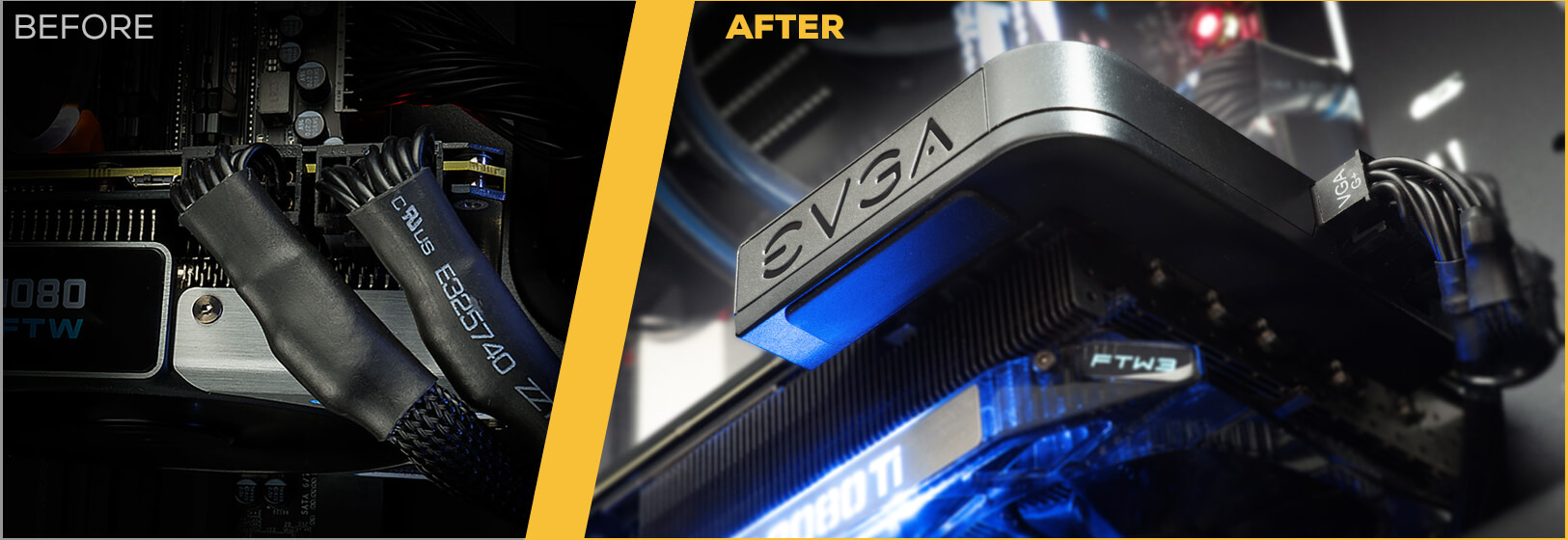
Honestly for a GPU which can cost in excess of $1600 they should have used something like the EVGA PowerLink which would have ensured power from the four 8 pin cables were balanced and would have attached securely to the card while also moving the power connectors themselves to the end, somewhere with much more room than the side,

before_after.jpg
 

InvalidError

Titan
Moderator
Honestly for a GPU which can cost in excess of $1600 they should have used something like the EVGA PowerLink which would have ensured power from the four 8 pin cables were balanced and would have attached securely to the card while also moving the power connectors themselves to the end, somewhere with much more room than the side,
Most 4090s are so long, many cases cannot fit the cards themselves without gutting the front of the case to make room.

You don't need an extra dongle to balance power between cables/wires, just split VRM phases on the board 3-7 ways between power pins + PCIe. The 3090FE did this, the 4090FE does not.
 

InvalidError

Titan
Moderator
Just use industrial grade power plugs standards nvidia for a $1600 card . not the cheapest of cheap !
Nvidia doesn't get to one-sidedly dictate what plugs its GPUs use, PSU manufacturers need to be on-board with whatever gets picked too and the PCI-SIG along with Intel's ATX spec also get a say in it.

The funniest thing about all of these failures is that nobody who has tried reproducing the melting connector issue has succeeded yet, which means that the melting connector problem is not caused by two wires breaking off from the connector, not caused by the connectors not being quite fully plugged in, not caused by any abuse within reason at least not within the testing period where connectors are allowed to reach whatever steady-state temperature they are going to reach under full load.

Since the problem cannot be pegged on any obvious combination of probable causes, we appear to be in uncommon manufacturing defect territory.
 
Oct 2, 2022
37
42
60
View: https://www.youtube.com/watch?v=EIKjZ1djp8c&t=1038s


Responsible in-depth reporting from GN, interesting that they are struggling to reproduce what Igor claims to have.

So, given you almost have to create this problem deliberately or through failure to plug something in properly, how likely is it that this is now subject to fake reports and deliberate damage because, well, internet trolls and fanboys? Not implausible in all fairness.

After all, we've already seen photos of smoking PS5's and Xboxs by people pushing cigarette smoke through the intake, reasonable to expect that some people might be happy to melt a cable for bizarre fanboy reasons having seen a single scenario where something went wrong.
 

cfbcfb

Reputable
Jan 17, 2020
96
58
4,610
For over a decade now I've watched companies with good products get screwed by a bean counter somewhere who picked a $2 ethernet or hdmi cable that didn't work out of the box, leading to product returns and customer dissatisfaction.

Nvidia sure turned that knob up to 11, didn't they? A $1600-2000 product hosed by a badly soldered cable.