
- Dec 1, 2016
- 5
- 0
- 4,510


I have the same problem as this guy
Here is a link to his pictures
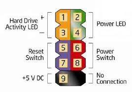
My old switch looks like this


2nd from the top left has no hole to match the one with no pin, so the left is the bottom, and the right is the top in the above pictures.
but the new one looks like this

These pictures came from someone who posted here...
But he never responded to say if it was fixed or how he got it fixed...I have a Dell Inspiron 3847 and have a new power button that has Power SW, Reset SW, HDD Led and Power Led. I know which are pos and neg, and I put it as shown here
but when I do that, I get it to power on with the sound of it powering on, but it doesn't turn the mouse, keyboard or screen on. The screen still says no signal, and the mouse and keyboard don't light up as they should. (those are the only things I used as indicators) I even unplugged all USBs & Took out the CR2032 button battery and the power plug at the back outside. (I didn't disconnect the power supply from the motherboard while I waited though (It wasn't suggested though)
The LED on the power button lights up fine.
Here's the kicker...If I take the cables out while it's still making the noise from me trying to get it to start up, and put the original cable block in, it turns on without me having to even press the original power button. The original one works, but because of a toddler who turns off the pc mid use, I need to attach this to it instead and keep it out of reach.


The switch is labeled, the motherboard isn't...and the manual only says Connect it, but not which one goes where because they assume you have one that's all together in one block, not separate.
Here's the Manual page 11, 38-39 (it's not even worth looking at this manual for you.)
None of these are my pictures, but if needed, I can post a picture of my specific motherboard.
Here are links to 2 videos to show you my connections etc more clearly. Sorry it's in 2 videos. I accidentally let my screen time out while moving while I had it paused, so I had to do a 2nd video.
What I said on the video was just my guess.
Video 1
Video 2
Here is a link to his pictures
My old switch looks like this
2nd from the top left has no hole to match the one with no pin, so the left is the bottom, and the right is the top in the above pictures.
but the new one looks like this
These pictures came from someone who posted here...
But he never responded to say if it was fixed or how he got it fixed...I have a Dell Inspiron 3847 and have a new power button that has Power SW, Reset SW, HDD Led and Power Led. I know which are pos and neg, and I put it as shown here
but when I do that, I get it to power on with the sound of it powering on, but it doesn't turn the mouse, keyboard or screen on. The screen still says no signal, and the mouse and keyboard don't light up as they should. (those are the only things I used as indicators) I even unplugged all USBs & Took out the CR2032 button battery and the power plug at the back outside. (I didn't disconnect the power supply from the motherboard while I waited though (It wasn't suggested though)
The LED on the power button lights up fine.
Here's the kicker...If I take the cables out while it's still making the noise from me trying to get it to start up, and put the original cable block in, it turns on without me having to even press the original power button. The original one works, but because of a toddler who turns off the pc mid use, I need to attach this to it instead and keep it out of reach.
The switch is labeled, the motherboard isn't...and the manual only says Connect it, but not which one goes where because they assume you have one that's all together in one block, not separate.
Here's the Manual page 11, 38-39 (it's not even worth looking at this manual for you.)
None of these are my pictures, but if needed, I can post a picture of my specific motherboard.
Here are links to 2 videos to show you my connections etc more clearly. Sorry it's in 2 videos. I accidentally let my screen time out while moving while I had it paused, so I had to do a 2nd video.
What I said on the video was just my guess.
Video 1
Video 2


