Momentary power switch wiring

smiley22432

Honorable
Mar 7, 2012
36
0
10,540
I'm trying to figure out the right way to wire a switch I purchased from performance-pcs. This is the diagram I was given:

switchdiagram.jpg


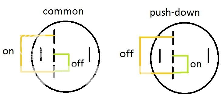
It has an odd number of pins so i'm a little confused on the correct way to put it. the far left and right pins are LED pins which is a no brainer.

This is what I think is the correct way. If it is not let me know please!

Hooking my power sw positive to the middle and the power sw ground to the bottom pin.
wiring.jpg
 

al360ex

Distinguished
Oct 15, 2010
300
0
18,810
Hello !

First off, what kind of switch did you buy ? A toggle switch (Common), a rocker switch or a push-down switch ?
The wiring will be different depending on the type of switch you have.

So before I can help you, I need to know exactly which kind of switch you have. If you could give me the model number or a link to the page on performance-pcs, it would be great.

Get back to me on this,
al360ex
 

ram1009

Distinguished


If there's a difference in the "on" & "off" diagrams I don't see it.
 

al360ex

Distinguished
Oct 15, 2010
300
0
18,810


It's not an "on" and "off" diagram. It simply shows the wiring for 2 different kinds of switch. The one on the left is for a toggle switch, and the one on the right is for a push-down switch. The wiring for theses switches are the exact opposite of one-another, because they work differently.
The diagram the OP made at the bottom is simply him asking if that is the correct wiring for his switch. Not knowing what kind of switch he has, I can't answer that yet.
 

ram1009

Distinguished


None of this makes any sense without further clarification. If the diagrams are NOT of on/off configurations (as you suggest) then why would they be labeled "on" "off"? The method of switch actuation (IE toggle, push button, rocker) is immaterial. All that's required is to know which contacts are made and not made in each switch position.
 

al360ex

Distinguished
Oct 15, 2010
300
0
18,810


Maybe my explanation was a bit vague...I'll try to do better this time.

On the diagram on the left (the one labeled "Common") the circuit will be closed when the switch will make contact with the top pin and the bottom pin. The circuit will be open when contact is made with the middle pin and the bottom pin.

On the diagram on the right (the one labeled "push-down"), it's the other way around. The circuit will be closed when the switch will make contact with the middle pin and the bottom pin. The circuit will be open when contact is made with the top pin and the bottom pin.

I think I've finally solved it.
If the OP's switch is of the type "Common", then the positive must be on the top pin and the negative on the bottom pin.
If the OP's switch is of the type "Push-Down", then the positive must be on the middle switch and the negative on the bottom switch.
 

ram1009

Distinguished
If it's a "standard push button momentary switch" as you say then use a ohm meter to determine which pins are closed when you hold down the button. Make sure those pins are open when you release the button. Attach your wires to those pins. Throw away the stupid diagram.
 

smiley22432

Honorable
Mar 7, 2012
36
0
10,540


thats exactly what I just did. Thanks!

I put the positive to the middle and the ground to the bottom just like i initially planned and it would get a reading only when I pushed the button in.
 

TRENDING THREADS