[SOLVED] Rail 12V -- PSU -- Amperage -- DC Jack

jumbo_trucker

Honorable
Dec 17, 2018
54
0
10,530
Hi,
I have a psu 250w fsp
which has 2 12v rails with different amperage
one to 8A and the other to 14A (+ 12V1DC-8A or + 12V2DC-14A)

I do not know how to recognize the cables from the color
since they are all yellow and there is no yellow-black cable
yellow +12v 8A
yellow/black +12v 14A

if you can identify the two 12v cables with different amperage, connecting them together would result in a current of 14 + 8 = 22A
correct?

there is also written on the psu + 12v-0.8A (DC JACK)
this is not clear what it is given that I do not see any jack connected to the psu

do the modern psu have 12v rails with different amperage?

Thanks
Regards
 
Solution
What's your PSU model or part number? So i can look up it's specs and pics to figure out which cables to connect.

As far as multi-rail PSU goes, provided that you can identify two PCI-E cables using different +12V rail, you can combine amps to properly power your GPU. Though, many multi-rail PSUs have one 12V rail for 24-pin ATX and 4/8-pin EPS12V connectors (those plug to your MoBo) while 2nd 12V rail is solely for PCI-E cables (to plug to your GPU). Hence the need for PSU specs to figure it out.

+ 12v-0.8A (DC JACK), while uncommon for PSUs, is the source for low amperage DC power directly from your PSU to power e.g LED strip, LED string lights, wireless router, ADSL cats, HUB switches, security cameras etc. In an essence, what...
What's your PSU model or part number? So i can look up it's specs and pics to figure out which cables to connect.

As far as multi-rail PSU goes, provided that you can identify two PCI-E cables using different +12V rail, you can combine amps to properly power your GPU. Though, many multi-rail PSUs have one 12V rail for 24-pin ATX and 4/8-pin EPS12V connectors (those plug to your MoBo) while 2nd 12V rail is solely for PCI-E cables (to plug to your GPU). Hence the need for PSU specs to figure it out.

+ 12v-0.8A (DC JACK), while uncommon for PSUs, is the source for low amperage DC power directly from your PSU to power e.g LED strip, LED string lights, wireless router, ADSL cats, HUB switches, security cameras etc. In an essence, what you'd have is this,
image:
814RCiNfiXL._SL1500_.jpg

But without the need to use power adapter that goes to the wall. Instead, you can take the DC power directly from your PSU.


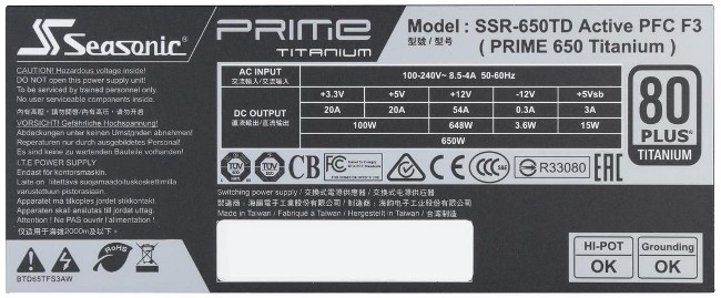
Modern PSUs usually are single-rail since compared to the multi-rail, single-rail offers better voltage stability. This is useful for CPU/GPU OC where you need to have voltages just right. For example, here's my Skylake build's PSU label,
image:
5390894.jpg

As you can see, my Seasonic PRIME 650 80+ Titanium is single-rail PSU.

There are few modern multi-rail PSUs out there. E.g Thermaltake Toughpower Grand 1200w,
image:
main.php

With one rail 40A and 2nd rail 85A.

Multi-rail PSU has better Over Current Protection (OCP) than single-rail PSU. This is useful if the PSU rated wattage is more than 1kW (1000W). However, many PSU brands don't use multi-rail in their 1+kW unit due to the voltage stability issues, e.g Corsair AX1500i is single-rail,
image:
8a-Nameplate.jpg


And so is Seasonic PRIME 1300 80+ Platinum,
image:
57_bbc3a404-326d-4656-9df0-4cab2bc8ba1d.jpg


80% or so of modern PSUs are single-rail.
 
Solution


Hi,
this is the psu
model : FSP250-60PNA-E(PF) FSP GROUP INC.

I would like to put an image but I did not understand how to do it


Hi,
thanks

I would like to understand well the various cables how many amps bring since they are all yellow 12v

 
Here's the PSU label of your PSU,
image:
mrxv5dU.jpg

As seen from label, 1st 12V rail should only have yellow wires while 2nd 12V rail should have black and yellow wires.

I also found images of the PSU, to make out how many and which power connectors it actually has. Best image i found is this,
image:
2rK7uIy.jpg

From the image, i can make out that PSU has following cables and connectors:
cable 1: 20-pin ATX (12V1 rail)
cable 2: 4-pin ATX (12V2 rail)
cable 3: 2x molex
cable 4: 2x molex
cable 5: 1x molex + 1x 4-pin floppy

There are no PCI-E connectors on that PSU which you can connect to the GPU. The 4-pin ATX (2nd 12V rail) is used to power the CPU. Then again, PSU is only 250W max and it's quite common to see such low wattage PSUs not having any PCI-E connectors.

If you want to power GPU in your PC as well, you will need to buy new and higher wattage PSU. But without knowing your GPU make and model, i can't suggest proper wattage PSU. So, which GPU you're planning to go for?


none gpu for now I'm going to buy

I needed to understand the amperage of the various cables

because the two-way 12v are only of a single yellow color

they can not be distinguished with the yellow / black ones

-I would like to put my personal images that I have on the pc. you could kindly tell me how to do it. so 'from my photos you can see better and is more' realistic compared to photos taken on the internet.

however, this is the psu

-as you can say with certainty that the first 12V 8A rail is on the 24-pin molex while the second 12V 14A rail is on the 4-pin.
since they are all yellow?

I think I will measure them with a dmm.

-still I do not know where the jack connects.

-to these which voltage and amperage arrive?
(cable 3: 2x molex
cable 4: 2x molex
cable 5: 1x molex + 1x 4-pin floppy)


Molex and floppy connectors have 12V rail and 5V rail. 5V rail amperage is 18A and 12V rail amperage should be 14A.

To put it short:
molex: 12V @ 14A and 5V @ 18A
floppy: 12V @ 14A and 5V @ 18A


How do i know why that 4-pin ATX cable is 12V2 (14A) and not 12V1 (8A)? Here's how:

Older computers put most of their load on 3.3 and 5 volts. As time passed, computers drew more and more of their load from 12 volts. Before this (4-pin ATX) power cable was introduced there was just one 12 volt line provided to the motherboard. This cable added two more 12 volt lines so more of the load could be shifted to 12 volts. The power coming from this connector is usually used to power the CPU but some motherboards use it for other things as well. The presence of this connector on a motherboard means it's an ATX12V motherboard. For dual 12 volt rail power supplies, this connector provides the voltage referred to as 12V2.

If you have one of these connectors on a motherboard then you must plug a power cable into it or your CPU won't get any power. The one exception is that when this connector was new, some motherboards shipped with a socket into which you could plug a molex cable as an alternative. That helped people who had older power supplies which didn't have the 4 pin 12 volt cable.
source: http://www.playtool.com/pages/psuconnectors/connectors.html#atx12v4


You can upload your images e.g here and post the image link in your reply,
image hosting: https://postimages.org/


thanks
this is the psu
https://i.postimg.cc/2SQfnM1W/psu-fsp.jpg


no you're wrong the image is of my cell phone and then I cut it is loaded on the site and I copied the link but I would like to see it directly. I did not take the image from the internet

there are other from my phone (not net image):
https://postimg.cc/HrjfDZd0
https://postimg.cc/DJfrHDKn

at the moment the 24-pin one does not use it or the 4-pin one

the yellow + 12V I think I took it from somewhere else
maybe from here
cable 3: 2x molex
cable 4: 2x molex
cable 5: 1x molex + 1x 4 pin floppy

I'm not sure which of the 3 is because after they were cut and isolated

considering that
molex: 12V @ 14A and 5V @ 18A
floppy: 12V @ 14A and 5V @ 18A

then it is likely that there are 14A from the yellow + 12V cable I am using

I could verify with certainty with a DMM putting in amperage.
do you know how to do?

is it possible that he wrote a wrong word on the psu plaque (yellow / black cable) or or that at the moment is it discolored?

 
Can you make a pic of your PSU connectors where each cable is separately placed and all the connectors are visible?
Similar to this pic:
image:
hs_S12_II_032.jpg

This way, it would be easier to figure out which wire has it's connectors removed.

As far as using the DMM (Digital Multi-Meter) goes, here, i don't know how to use it since i don't have one.

Also, it is possible that PSU label is wrong since it's hard to understand older PSU labels due to their complexity.


I know how to use a Dmm only that I have never used one to measure the amperes on a psu per pc.
I would not do damage.
https://i.postimg.cc/rsSYKXKh/fsp-wires-psu.jpg

counting the cables you have in total
5 blacks
3 yellows
3 reds
(excluded 24 pin and 4 pin)

1 yellow and 1 black used to feed a load


Wow, someone has butchered the PSU power cables quite heavily and removed all the connectors, except 20-pin and 4-pin.

Those loose cables you have, those are:
black: ground
red: +5V rail (18A)
yellow: +12V rail (14A)
green: PS_ON# (used to turn PSU on and off, should be connected to 20-pin connector)

It looks like the green and black wires have connector on them and switch as well, for PSU manual turn on/off.

Here, i'd buy a new PSU. Besides missing most of the connectors, the thing with old PSUs is, that the older they are - the higher the chance of them dying is. But if you want to use your old FSP PSU then do that on your own risk.


that someone would be me

and I am aware and responsible for what I do.

I know the colors of the cables and I know what they mean

those are old pictures now the cables I have arranged them better

and I put a switch between green and black to turn on the psu

and as I told you I used yellow and black to feed a load

however, in the end I solved
I used the dmm and I identified the various amperages and contrary to what was said

the 4-pin ones are the 14A ones

while the other yellows are at 8A (there are 2 different amperages for the yellow 12V cables. they are not always at 14A. in fact, this was always the question from the beginning.)

so now I'm using those at 12V 8A (while if I used the 4-pin one I would have a maximum amperage of 14A)

thanks

"Those loose cables you have, those are:
black: ground
red: +5V rail (18A)
yellow: +12V rail (14A) This is wrong the free yellow cables in the photo are 8A no to 14A (4pin)
green: PS_ON# (used to turn PSU on and off, should be connected to 20-pin connector)"

 
1st, you have to locate that +12V 0.8A wire coming from PSU. Once you've done that and using ground wire as well (black sleeving), use can use that to power any peripheral that doesn't consume more than 0.8A.

E.g standard 120mm LED fan operates at +12V and 0.3A. Though, connecting a fan to the PSU will result fan spinning at 100% all the time.

thanks
understood is the word DC JACK that has misled me since there is no jack on the PSU
what color do you think is the cable?
(then I check with the DMM clamper)

they told me that this psu has the regulators of + 12V 8A and + 12V 14A separated
what do you think about it?
since I know that the new PSUs have + 12V rail and then DC-DC converters create 3.3V and 5V rails
maybe this psu fsp is old and it does not use DC-DC converters to generate the minor lines and therefore has separate + 12V regulators
 
Older PSUs are usually using group-regulated design rather than DC-DC conversion design and here, i think that your FSP unit is also group-regulated.

Since you cut off most of the PSU power cable connectors, i have 0 clue what color that +12V 0.8A wire could be. It might be yellow, it might be something else.


thank you
no problem
I will find the DC jack using a DMM clamper
I had to cut them because otherwise if I stayed them of that length there was the risk of creating sparks or worse fire
in fact, they advised me to cut them about 2.5 "so as not to risk possible fires according to what they told me
but honestly it is the first time I hear this and it is also the first time I try to use an old power supply for PC to power a 12V load. so for the moment I have to base on different info and advice hoping both fair and truthful information

if you have any other advice about cable length or securing the psu it would be better

for the moment I placed the psu on a wooden shelf
this should already be sufficient for earth protection since the socket has the ground cable