[SOLVED] Watercooling flow direction - slight confusion / CPU inlet/outlet

Owen O

Reputable
Mar 31, 2016
14
0
4,510
Hi there,
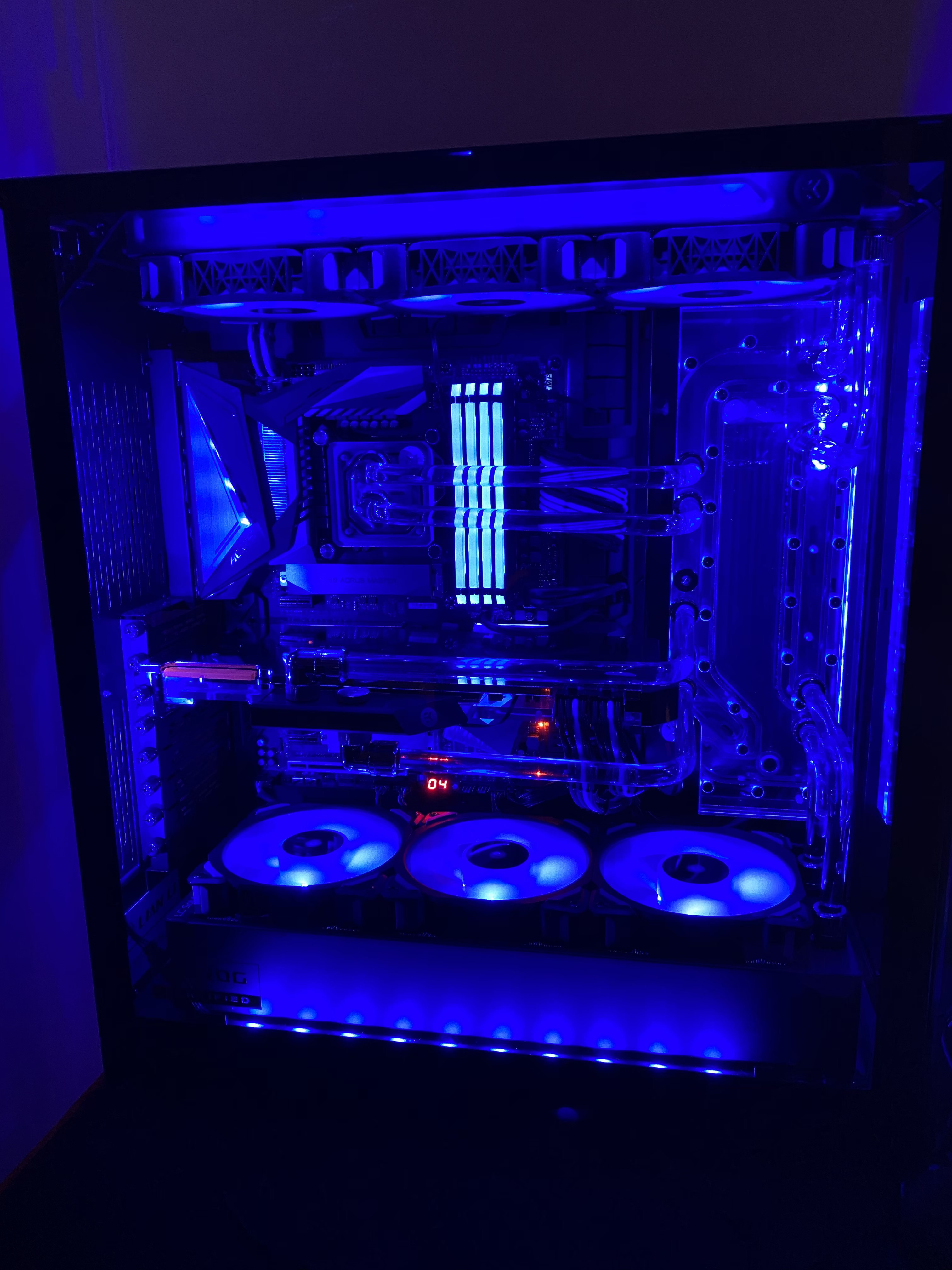
I ran my first water-cooled loop just over a week ago now using the Lian-Li dynamic xl case.. Images below to give you an idea

https://ibb.co/2vTht2R
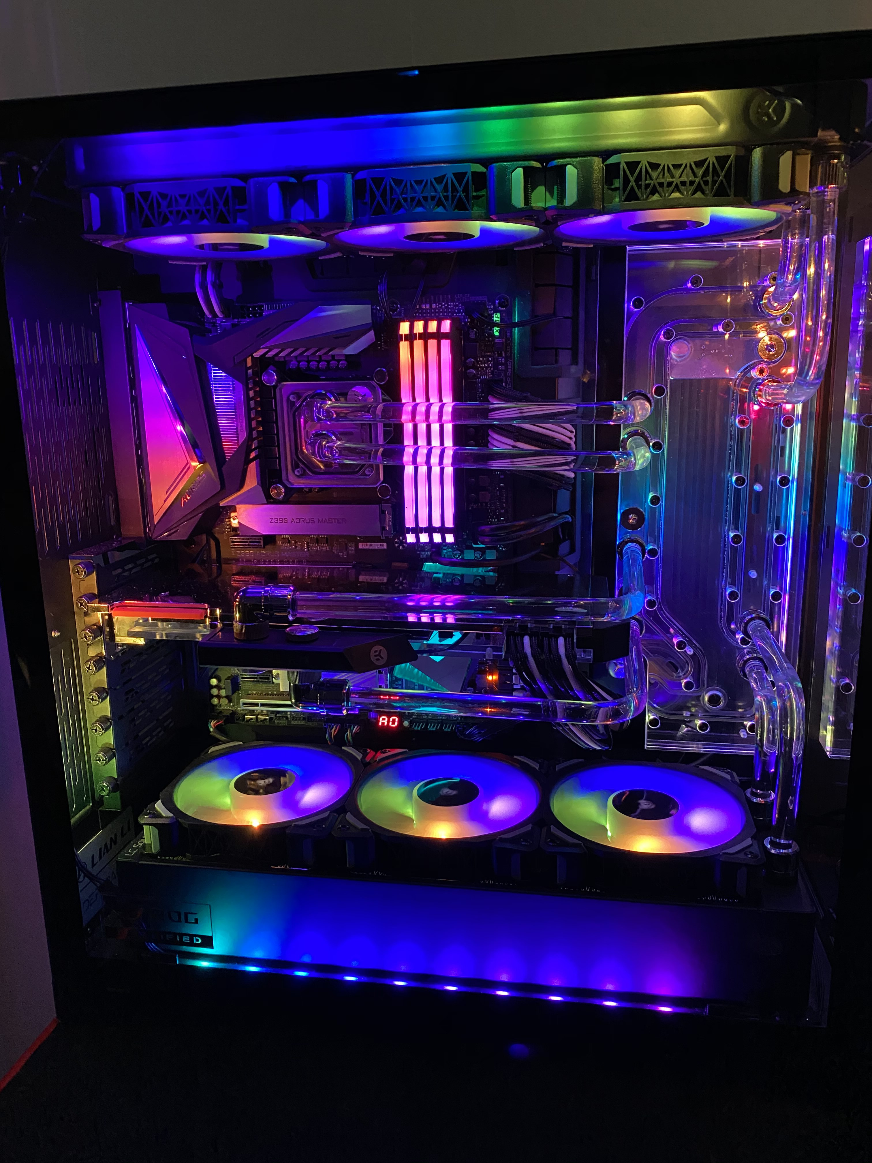
https://ibb.co/pPxr8c6

now I'm having to RMA the CPU block as the RGB is broken but it got me looking at a few things.. At the time of installation, I didn't seem to notice there was an arrow on the block that seems to be indicated on the online manual https://www.ekwb.com/shop/EK-IM/EK-IM-3831109810347.pdf

I have the D-RGB version (https://www.ekwb.com/shop/ek-velocity-d-rgb-nickel-plexi ) so I'm not sure why this would differ from the one illustrated in the manual

Apparently after much googling, because it has the jet thing inside its important to ensure this goes in properly, but as I'm using the Lian-li distro block I'm trying to work out exactly the flow direction... From what I can see on the manual https://www.ekwb.com/shop/EK-IM/EK-IM-3831109822128.pdf (PAGE 5) the outlet which I presume is the outlet from the reservoir and not where the outlet should come in to...

Has anyone any experience with this particular setup or can advise? Is it true that it has to go in through the specific inlet/outlet which would make sense why my temps has been slightly higher than I initially expected (high 60's in long gaming sessions), prime 95 it started to throttle and this is at stock speeds i9 9900k with the regular 4.7 ghz turbo.

If so which direction is the flow on this unit? am I right in thinking the top would where the cpu block inlet should be..
 
Last edited:
Solution
For the CPU block it doesnt matter if the outlet is on the top or bottom, as long as the inlet is in the center then everything is fine.

If the outlet for the cpu was on the bottom then you/they would have had to cross the hard tubing over each other to get to the right port on the distrbution

Owen O

Reputable
Mar 31, 2016
14
0
4,510
you need to look at page 6 since you're running 2 radiators.


Everything im looking at seems to match up correctly.

https://www.ekwb.com/shop/EK-IM/EK-IM-3831109810347.pdf

when I look at that though it seems to suggest the inlet (page 8) is on the bottom, and the outlet on the top in the current way I have it seated with the velocity sign on the right.

When I googled it I notice quite a few people seem to have this setup but would appear to be wrong if I'm looking at it correctly from the PDF above?

So I'm wondering whether the velocity sign should be on the left instead if that makes sense...

The instructions don't seem to fill me with confidence either way, I thought it wouldn't make much difference whether the flow was reversed but people on forums seem to suggest that because of the jet plate gasket that it is imperative it's done correctly
 
For the CPU block it doesnt matter if the outlet is on the top or bottom, as long as the inlet is in the center then everything is fine.

If the outlet for the cpu was on the bottom then you/they would have had to cross the hard tubing over each other to get to the right port on the distrbution
 
Solution

Owen O

Reputable
Mar 31, 2016
14
0
4,510
For the CPU block it doesnt matter if the outlet is on the top or bottom, as long as the inlet is in the center then everything is fine.

If the outlet for the cpu was on the bottom then you/they would have had to cross the hard tubing over each other to get to the right port on the distrbution

ok thanks, I appreciate it

I think my confusion came because for some reason in my head I've confused the flow direction thinking it was coming from top-down the way, rather than what is actually happening is:

Reservoir -> Pump -> Gpu -> Cpu ->Rad 1 -> Rad 2 -> REPEAT

I had it in my head the CPU was first for whatever reason

{ edit - for confusion sakes.. I did try to make it clear in a follow up post that the "reservoir" was just channels CNC into the acrylic but felt it best to relabel the loop in case it caused confusion }
 
Last edited:
Reservoir -> Pump -> Gpu -> Reservoir -> Cpu -> Reservoir -> Rad 1 -> Reservoir -> Rad 2 -> REPEAT

In a nutshell yes, the tubes do come back to the block between parts but the water runs in a predetermined channel around the reservoir. It only returns to the reservoir once it leaves the second radiator.
 

Owen O

Reputable
Mar 31, 2016
14
0
4,510
Reservoir -> Pump -> Gpu -> Reservoir -> Cpu -> Reservoir -> Rad 1 -> Reservoir -> Rad 2 -> REPEAT

In a nutshell yes, the tubes do come back to the block between parts but the water runs in a predetermined channel around the reservoir. It only returns to the reservoir once it leaves the second radiator.

yes the routes have been CNC out I understand :)

must be some CNC machine to do it too, the CNC in our work is generations behind for sure
 
What Rubix said is correct. For small volumes of water and volumes moving at high speed through a loop, the liquid is all the same temp, effectively. That's physics. Jayz2cents did a video on that relatively recently where they went through several combinations of loop orders and measured temps. Each loop order was within the margin or error of all the other loop orders.

For clarity of anyone coming here to look at the loop order listed above. I will point out that the distro block has multiple chambers and that loop orders listed above are not accurate. Or at least poorly labeled. The distro channels are not connected of the res. You'd never get flow through a loop that returned to the res so often as listed above. The distro channels are just "tubes" and not part of the res.

The loop as drawn (which I believe to be correct) is:

Pump-GPU-(distro channel)-CPU-(distro channel)-top rad-(distro channel)-bottom rad-res-pump.
 

rubix_1011

Contributing Writer
Moderator
Yep, most distribution blocks are essentially just a re-route of tubing that fills a larger, physical gap of space. If you look closely at the channels being routed, you can mentally just picture them as a different link of tubing; nothing more.

The distribution block gets creative by having a single piece of acrylic that does all of this, but likely for multiple 'routes', but only for the primary reason of aesthetics, not for convenience or acting as a 1-to-many reservoir. Each port is almost always a 1:1 to another single port.
 

Owen O

Reputable
Mar 31, 2016
14
0
4,510
What Rubix said is correct. For small volumes of water and volumes moving at high speed through a loop, the liquid is all the same temp, effectively. That's physics. Jayz2cents did a video on that relatively recently where they went through several combinations of loop orders and measured temps. Each loop order was within the margin or error of all the other loop orders.

For clarity of anyone coming here to look at the loop order listed above. I will point out that the distro block has multiple chambers and that loop orders listed above are not accurate. Or at least poorly labeled. The distro channels are not connected of the res. You'd never get flow through a loop that returned to the res so often as listed above. The distro channels are just "tubes" and not part of the res.

The loop as drawn (which I believe to be correct) is:

Pump-GPU-(distro channel)-CPU-(distro channel)-top rad-(distro channel)-bottom rad-res-pump.

edit - for confusion sakes.. I did try to make it clear in a follow up post that the "reservoir" I listed was just individual channels CNC into the acrylic but felt it best to relabel the loop in case it caused confusion for people coming in through google etc.

Thanks guys :)

I had watched many videos about flow direction and I do agree that the loop order will not matter in any way, Jayz all but confirmed that among others however on the CPU block it does have a specific inlet and outlet and does look like it has to be done in that specific way due to the jet plate you will get better performance supposedly

https://www.ekwb.com/shop/EK-IM/EK-IM-3831109810347.pdf

it even says specifically on the instructions:

"With EK-Velocity series water blocks it is mandatory to use the port that is nearest to the center of the water block as INLET port. Mixing the ports may result in less than ideal thermal performance of the water block."
 

rubix_1011

Contributing Writer
Moderator
Most CPU blocks do have a dedicated inlet and outlet. EK blocks usually also use a specific jet plate configuration to orient flow over the CPU cores appropriate for the processor and socket in question....which might require disassembly and reconfiguration.