Question 3600mhz CL16 RAM not stable on 3900X

Page 2 - Seeking answers? Join the Tom's Hardware community: where nearly two million members share solutions and discuss the latest tech.

_C_H_R

Prominent
Jan 13, 2022
26
3
535
Hi all, recently I just made an upgrade on my Memory from Ramaxel 48gb 2400mhz cl18 to Kingston Fury Renegade 216gb 3600mhz cl16 - KF436C16RB1AK2/32. There are 2 XMP profiles available 1: DDR4-3600 CL16-20-20 @1.35V, and 2: DDR4-3000 CL15-17-17 @1.35V. I started with the first one, caused me 4 BSOD within 2 days and I swtiched to profile 2 which seems to resolve all the problems/instabilities. I was wondering what would be the problem for system being instable at 3600mhz cl16? Should try to manually OC to 3200mhz and lower cl such as 14-14-14? or let it stay on profile 2? another weird thing is from the Specifications page of Kingston it says that profile 2 comes at CL15-17-17 but from CPUZ it shows as 16-17-17.

Here are my specs:
Operating System Microsoft Windows 10 Pro x64
CPU Type 12-Core AMD Ryzen 9 3900X, 4550 MHz (45.5 x 100)
Motherboard Name MSI MPG X570 Gaming Pro Carbon WiFi (MS-7B93) (2 PCI-E x1, 2 PCI-E x16, 2 M.2, 4 DDR4 DIMM, Audio, Video, Gigabit LAN, WiFi)
Motherboard Chipset AMD Bixby X570, AMD K17.7 FCH, AMD K17.7 IMC
System Memory 32720 MB
DIMM3: Kingston KF3600C16D4/16GX 16 GB DDR4-3000 DDR4 SDRAM (16-17-17-36 @ 1500 MHz)
DIMM4: Kingston KF3600C16D4/16GX 16 GB DDR4-3000 DDR4 SDRAM (16-17-17-36 @ 1500 MHz)
BIOS Type AMI (01/14/2020)
Video Adapter NVIDIA GeForce GTX 1080 (8 GB)
Case TUF Gaming GT501
CPU Cooler Cooler master masterliquid 360r rgb
PSU I dont know the model, but its 600-650W.

Huge thanks to all of you that spent time reading this.
 
Last edited:

Karadjgne

Titan
Ambassador
The QVL is pathetic, really. It's just a list of a couple sticks the vendor tried. The only important info being the actual speeds tested. It's highly doubtful you'll get a stick that matches because the model numbers are all different.

If you look at gskill Trident-Z, the blue ones have one model number for a single stick, another for a 2 stick kit, another for a 4 stick kit. As do the reds, grays, blacks, black/white, black/silver, camo, rgb etc. And that's not including the different models for different timings and speeds and capacity in all those colors. There's over 5000 individual model numbers in just DDR4 Trident-Z.

Nobody will test them all, plus the RipJaws, plus every line corsair has, Kingston, Adata, SkHynix, and others. The QVL would be thousands of pages long and take a team of testers a massive amount of time, on every board in the lineup.

So they only test half a dozen per speed.
 
  • Like
Reactions: boju and _C_H_R
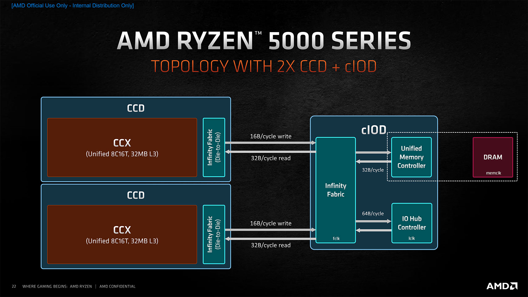
hi, your nb and mem controller clocks are set to 1800MHz...which is ok for max performance, but since its unstable, then you wont know if unstability comes from ram or from CPU infinity fabric/mem controller

so go to bios and unlink it, thats the FCLK and UCLK. reduce it to 1600MHz for now (official supported speed)
keep XMP 3600 enabled and run memtest or aida stress test
if no errors, then youll just need to correct voltages for infinity fabric or mem controller (depends on which one is unstable)
 

_C_H_R

Prominent
Jan 13, 2022
26
3
535
hi, your nb and mem controller clocks are set to 1800MHz...which is ok for max performance, but since its unstable, then you wont know if unstability comes from ram or from CPU infinity fabric/mem controller

so go to bios and unlink it, thats the FCLK and UCLK. reduce it to 1600MHz for now (official supported speed)
keep XMP 3600 enabled and run memtest or aida stress test
if no errors, then youll just need to correct voltages for infinity fabric or mem controller (depends on which one is unstable)

Hi, the question now is not even 3600mhz... After all the unstable and effort made on tweaking voltage (SoC to 1.1 and 1.5, DRAM to 1.38-1.39 + set manually FCLK to 1800)I gave up on 3600 and went with Memory Try It! (feature of msi mb) that has an option of 3200mhz cl 16-16-16 and guess what.... still unstable.... which is rly suspicious... During the process when I tried an option of 3200mhz with cl14 my PC wont display image, so I cleared CMOS, and put back my old 4*8gb sticks of 2400mhz cl17. I ll try these 3600 sticks tomorrow on my friends PC which is 11400f+b560m and running 3200mhz cl16 currently, if it keep crashing I think I have to return those and go with a better manufacturer? :///
 
Hi, the question now is not even 3600mhz... After all the unstable and effort made on tweaking voltage (SoC to 1.1 and 1.5, DRAM to 1.38-1.39 + set manually FCLK to 1800)I gave up on 3600 and went with Memory Try It! (feature of msi mb) that has an option of 3200mhz cl 16-16-16 and guess what.... still unstable.... which is rly suspicious... During the process when I tried an option of 3200mhz with cl14 my PC wont display image, so I cleared CMOS, and put back my old 4*8gb sticks of 2400mhz cl17. I ll try these 3600 sticks tomorrow on my friends PC which is 11400f+b560m and running 3200mhz cl16 currently, if it keep crashing I think I have to return those and go with a better manufacturer? :///
nah its just some small setting for sure
those CPUs are capable of running really nice memory clocks, 3600MHz is doable even on bad CPU sample
mine 3200MHz CL14 sticks on X370board (which was supposed to tops out at 3200MHz) are running fine now at 3733MHz CL16 1.35v
but i had to tweak cpu voltages a little, otherwise ram would top out at 3533MHz when running in 1:1 mode


your case might be different, but if you run ram in 1:1 mode (FCLK=MCLK=UCLK=1800). then you overclocking 3 different things at same time (memory controller, infinity fabric and ram itself)
to rule out FCLK/UCLK instability (inside CPU), just set them to their max supported non overclocked values (1600MHz)
then enable XMP
dont touch anything else (no voltage/timings change), see how stable it is

if XMP is stable, keep raising FCLK/UCLK untill unstable, once unstable, raise voltages a little
min - max for 3600MHz
SOC - 1.00 -1.10v
VDDG - 0.95 - 1.05v (keep it -0.05v lower than soc for max value)
CLD0 - 0.70 - 1.05v (max value same as above)

if XMP unstable, you can either reduce ram clock, alter memory timings or add ram voltage
 
  • Like
Reactions: _C_H_R

Karadjgne

Titan
Ambassador
Ryzen love faster memory. They use it differently to Intels. They actually get usage out of the speeds. The F clocks are the speeds the cores use to communicate between each other. The Fclock uses the Data Rate of the ram as it's clock speed.

So, faster the ram, higher the Fclock, faster the cores can communicate, stronger and faster the performance of the cpu at its operating frequency. Just a bump from 2133MHz to 3200MHz equates to roughly a 20% performance increase. That has bonuses in everything from map loading times, boot times, app speeds to do stuff, windows 'snappiness' even to gaming fps.
 
to rule out unstable memory controller or infinity fabric?

What does it matter? They are links of the same chain, and (therefore) the effective speed would be the slower of them. The switch-fabric steers data lanes, memory controller performs memory reads/writes, they work together and having them at different speeds can potentially degrade performance, not improve (due to different loop cycle completion time). I am not convinced.

arch15.jpg


The F clocks are the speeds the cores use to communicate between each other.
What do separate cores communicate to each other? What are you talking about? Are you quoting something? Some specific application?
 
Last edited:
What does it matter? They are links of the same chain, and (therefore) the effective speed would be the slower of them. The switch-fabric steers data lanes, memory controller performs memory reads/writes, they work together and having them at different speeds can potentially degrade performance, not improve (due to different loop cycle completion time). I am not convinced.
pls re-read first post
 

_C_H_R

Prominent
Jan 13, 2022
26
3
535
You really need to make sure the BIOS is up-to-date.
Yes it is up to date since firsts voltage tweak didn't work. and still nothing... I ll follow what kerberos_20 said about unblinking FCLK and UCLK first to spot which instability is in question cause today I tried these sticks on 11400f+b560m it worked out smooth however when stressing the CPU 11400f MHz doesn't pass 3100MHz which is weird...
 

_C_H_R

Prominent
Jan 13, 2022
26
3
535
nah its just some small setting for sure
those CPUs are capable of running really nice memory clocks, 3600MHz is doable even on bad CPU sample
mine 3200MHz CL14 sticks on X370board (which was supposed to tops out at 3200MHz) are running fine now at 3733MHz CL16 1.35v
but i had to tweak cpu voltages a little, otherwise ram would top out at 3533MHz when running in 1:1 mode


your case might be different, but if you run ram in 1:1 mode (FCLK=MCLK=UCLK=1800). then you overclocking 3 different things at same time (memory controller, infinity fabric and ram itself)
to rule out FCLK/UCLK instability (inside CPU), just set them to their max supported non overclocked values (1600MHz)
then enable XMP
dont touch anything else (no voltage/timings change), see how stable it is

if XMP is stable, keep raising FCLK/UCLK untill unstable, once unstable, raise voltages a little
min - max for 3600MHz
SOC - 1.00 -1.10v
VDDG - 0.95 - 1.05v (keep it -0.05v lower than soc for max value)
CLD0 - 0.70 - 1.05v (max value same as above)

if XMP unstable, you can either reduce ram clock, alter memory timings or add ram voltage
Thanks in advance! I tried these memory sticks on 11400F+B560m and it worked without instability, however during stressing test 11400F CPU Clock didn't pass 3100MHz which is weird bc it should be at smth like 4400MHz... but no instability spot. Ill follow ur guide by tomorrow to see if I can spot the problem. btw where should I set UCLK? I didn't see it in BIOS I think just FCLK and RAM Mhz
 
pls re-read first post
I did, it says there are memory errors when it is set to work at 3600 (which is ~12% overclock for the CPU memory interface).
It could be tweaked to run a little faster as long as it is symmetric (1:1) and will maybe yield marginal overall performance improvement.
And I truly do not get what would be wrong with running it at AMD recommended speed which is 3200.
To shed some light into it, would you run Geekbench test with your memory settings and compare them to plain 3200 (given the rest is same and 5000 ryzen), just to see what improvement it really gives if any?
 
Last edited:
I didn't see it in BIOS I think just FCLK and RAM Mhz
UCLK is AMD term for memory controller clock setting.
11th gen Intel has different memory specs, it will take modules up to 4266 natively, and it would not have memory controller speed setting separate from memory speed.
As for stress testing and 3.1GHz, you would want to look into thermal envelope and boost settings, it is not memory related.
 

_C_H_R

Prominent
Jan 13, 2022
26
3
535
UCLK is AMD term for memory controller clock setting.
11th gen Intel has different memory specs, it will take modules up to 4266 natively, and it would not have memory controller speed setting separate from memory speed.
As for stress testing and 3.1GHz, you would want to look into thermal envelope and boost settings, it is not memory related.
I think its TDP limit from 11400f which is 65W that goes only up to 3100MHz. So, the only conclusion I can take from testing it on intel is that the ram sticks itself is fine but does not work on my AMD setup right?
 

Karadjgne

Titan
Ambassador
No quite. There's a big difference between works out of the box, works with tinkering and does not work.

You could even get 2 more sticks, a different model by a different vendor, and still run into the same issue. If the ram works without issue or error in the Intel mobo, it'll work without issue or error in your pc, the issue not being the ram but some other factor.

That could be anything from a bent cpu pin to improper cpu cooler mounting pressure to a weak memory controller or any combination of the above, or other things not tried or tested for yet.
 

_C_H_R

Prominent
Jan 13, 2022
26
3
535
No quite. There's a big difference between works out of the box, works with tinkering and does not work.

You could even get 2 more sticks, a different model by a different vendor, and still run into the same issue. If the ram works without issue or error in the Intel mobo, it'll work without issue or error in your pc, the issue not being the ram but some other factor.

That could be anything from a bent cpu pin to improper cpu cooler mounting pressure to a weak memory controller or any combination of the above, or other things not tried or tested for yet.
I see, but aside from tweaking bios setting and such, what should I do with those physical things that may impact the result? I mean my cooler works out great despite a bit of noise, it leaves 3900x between 73-80C when stressing with new RAM. and 40 on idle (currently I'm using the old 2400mhz 4 sticks ram).
 
I think its TDP limit from 11400f which is 65W that goes only up to 3100MHz. So, the only conclusion I can take from testing it on intel is that the ram sticks itself is fine but does not work on my AMD setup right?
Correct. Does not work at selected XMP profile setting of 3600.
I would try setting everything manually to 3200 using voltage and delays from 3600 profile (16-20-20 @1.35V ?) and leaving the CPU settings intact at this point to see if that works first. Then try improving it while keeping things 1:1 if you do chase the last 2% performance cents.

As for the Intel part, try setting a voltage offset for the CPU of say -0.05v in BIOS and it will boost much better with the same 65W limits. If stable, try -0.085v etc till you find the highest negative offset while staying stable.
 
Last edited:

_C_H_R

Prominent
Jan 13, 2022
26
3
535
Correct. Does not work at selected XMP profile setting of 3600.
I would try setting everything manually to 3200 using voltage and delays from 3600 profile (16-20-20 @1.35V ?) and leaving the CPU settings intact at this point to see if that works first. Then try improving it while keeping things 1:1 if you do chase the last 2% performance cents.

As for the Intel part, try setting a voltage offset for the CPU of say -0.05v in BIOS and it will boost much better with the same 65W limits. If stable, try -0.085v etc till you find the highest negative offset while staying stable.
I got the 3200mhz part, but regarding intel one shouldn't I increase TDP? or CPU voltage rather than decreasing it? Or am I misunderstood?
 

Karadjgne

Titan
Ambassador
The entire theory behind overclocking is to get the best performance for the lowest voltages and temps. Wattage is volts x amps, and there's no telling exactly how many amps a cpu will demand or need, as that changes with loads. The only somewhat stable supply is voltage, and that we can change.

If the pc is stable at 1.4v vcore at the speeds you want, what you can do is incrementally lower the voltage until the pc becomes unstable. That's the point of stress testing, to determine the point of instability. So you'd drop to 1.378v and try again etc.

With each successive drop in power demanded comes a respondent drop in temps. For instance, my i7-3770K could hit 5.0GHz at 1.42v and was pushing 88°C. Dropped the OC to 4.9GHz, voltage down to 1.308v and temps dropped to 72°C. Minor change in speeds, huge change in voltage and temps.

That applies to any component, be it ram or gpu or cpu. It's always advisable to lower voltages, if you can. If you cannot, then only raise them to the absolute minumum necessary. Ddr4 for instance can handle 1.5v, but that's only advised for maximum OC under LN2, world record attempts etc. Base voltage is set as 1.25v and most XMP profiles will generically use 1.35v. That doesn't always work, sometimes mobo/cpu combos require a little more juice in the ram, so you may need to bump dram to 1.38 instead.

Nothing is set in stone, there's no formula that's guaranteed, no procedure that's perfect. OC is OC and it's all about tailoring Your specific pc to get what you want. Even an identical system is different in so many little ways, each is truly unique.
 
  • Like
Reactions: _C_H_R
regarding intel one shouldn't I increase TDP? or CPU voltage rather than decreasing it? Or am I misunderstood?
No, you should not. Increasing the voltage means increasing the power. They have direct and non-linear relationship.
The reason it throttles down is that it needs to decrease power to stay within the envelope, so it steps down to a lower frequency that has a lower voltage value paired to it.
With Intel having dynamic voltage control, it works in a way that for every frequency increment it makes a voltage increment from a pre-defined chart. Sample.
You should not set it static - it will keep heating up the room even at a low workload.
What I suggest is having it dynamic and enjoying the benefit of low power modes being truly low power. See if you can offset the chart towards lower power consumption at all (including higher) workloads so it does not throttle down or does it less.
To do so, you would want to introduce a negative offset to the chart. How low can you go? It is your own silicon lottery ticket.
Nxl5Kvb.png

S6yUNsF.png
In short,
  • To achieve power saving and dynamic frequency/boost capabilities, there is a table of predefined Voltage:Frequency pairings for intel CPUs (that support it)
  • Higher Frequency requires Higher Voltage (as a general rule, to achieve sharper rising and falling edges you need higher deltas)
  • Higher Voltage yields higher power consumption (Watts = Volts * Volts/Resistance). At high workloads, resistance goes very low (0.02~0.01Ω ) and it is not dependent on frequency.
    • Example A: 1.3v*1.3v/0.013Ω=130W
    • Example B: 1.16v*1.16v/0.013Ω=103W
  • Lowering voltage by negative offset lets it stay higher up in the frequency table when reaching the power cap.
P.S. Same works for Turing and Ampere GPUs and there is an automatic OC scan feature to offset the table.
 
Last edited:

Karadjgne

Titan
Ambassador
The offset is not applied to vcore, it's applied to VID, which is entirely different.

VID (Voltage Identifier) = Voltage Level "request" by the CPU to the motherboard's VR (voltage regulator) to supply it, this is initialized by the CPU and can change accordingly if the CPU is in power saving mode like C1E/EIST features, and also each CPU has an unique max VID internally that was set at factory level while they're running at full load. Turning off power saving features like C1E/EIST will overide and disable those feature and the cpu's VID will be permanently set at their max.

VCore = Actual voltage "delivered/supplied" by the mobo to the cpu, this could be automatic from the cpu as the function of C1E/EIST features ... or ... it was manually set and override by user like in OCing, and this "manually set" vcore could be higher/lower than the cpu's VID at mobo with oc-ing capability.

When applying an offset, you lower the requested amount only. Ideally requested amount should remain 0.05v higher than supplied amount. This is the purpose of the offset, combined with LLC. For example: if vcore + LLC = 1.216v and VID = 1.208v, you'd need to supply a Positive offset of at least 0.14v to get supplied voltage above requested. If vcore + LLC was 1.108v, you could apply a Negative offset of 0.95v to bring VID closer to actual supplied voltages. The offset will change according to what LLC settings are enforced, part of the reason its recommended Not to apply Extreme or Max LLC settings or requested voltage will be considerably higher than what the cpu actually uses, which creates a much higher temp curve per load amount and stresses VRM's.
 
When applying an offset, you lower the requested amount only. Ideally requested amount should remain 0.05v higher than supplied amount. This is the purpose of the offset, combined with LLC. For example: if vcore + LLC = 1.216v and VID = 1.208v, you'd need to supply a Positive offset of at least 0.14v to get supplied voltage above requested. If vcore + LLC was 1.108v, you could apply a Negative offset of 0.95v to bring VID closer to actual supplied voltages. The offset will change according to what LLC settings are enforced, part of the reason its recommended Not to apply Extreme or Max LLC settings or requested voltage will be considerably higher than what the cpu actually uses, which creates a much higher temp curve per load amount and stresses VRM's.
This is incorrect, misleading, and very confusing. Let me try to reassemble it so it makes sense.
1. The Vcore curve is operated by the embedded voltage regulator. Not motherboard. CPU has it. (quoting 10th series Intel datasheet, volume 1, page 110, paragraph 12.1.2)

2. The embedded voltage regulator has the Vcc as its input, which is controlled by motherboard VRM. VID is a means to control this input, using a factory-calibrated chart, compensating for individual characteristics of the chip itself. Control is done using Serial VID bus between the chip and the board. (quoting 10th series Intel datasheet, volume 1, page 111, paragraph 12.1.3)

3. LLC... not a simple one to explain. Has absolutely nothing to do with Vcore curve.
In normal (not ideal) operation, CPU Core resistance varies significantly. In my example above between ~0.117Ω (at idle) and all the way down to ~0.011Ω at full load. That in turn causes current spikes from 8.54A to 87.4A in split second.
VRM is a switching power supply with feedback and it will always try to accommodate load variation and prevent voltage drop or overshoot, but it takes a few cycles, so as a result it will initially undershoot and/or overshoot the value it is set (by VID) to supply. After a few cycles (if the load stays constant) it will line up perfectly (aka damped harmonic oscillator chart). Very similar to driving on a bumpy road - you can't make it smooth if you do not know what is coming. VRM does not. For that very reason, the faster the VRM controller - the faster over/undershoots are gone and the line is perfectly stable. But the problem is... - the load is never constant.
  • Undershoot causes system instability due to insufficient CPU power during load spikes.
  • Overshoot causes excessive heating. High overshoot is capable of causing permanent damage.
"Loadline Calibration" is a means to deliver higher power (yields higher voltage if not heavily loaded) right after initial drop based on even higher load prediction, to compensate for initial undershoot, which "protects" from the undershoot case, but may cause (also high) overshoot if the load does not rise or immediately falls. The higher the value, the sharper will be the rise after the initial drop under rising load.

And even more issues in GPUs. Large Capacitor arrays under and right next to the chips are used to swallow those "road bumps", called decoupler circuitry.

What I proposed is offsetting the vCore curve.
  • For example (numbers are just random, too lazy to calculate exact values and percentages)
    • non-existent CPU has 4 consequent points on the curve (Frequency - vCore)
      • Point A: 100MHz, 1V (yields 60W for all cores at full load)
      • Point B: 120MHz, 1.2V (yields 70W for all cores at full load)
      • Point C: 140MHz, 1.4V (yields 80W for all cores at full load)
      • Point D: 160MHz, 1.6V (yields 90W for all cores at full load)
        • If the CPU is limited to 65W, it will have to roll back to point A under continuous full load in order to comply with the limit.
    • If we offset the voltage using -0.2, it becomes
      • Point A: 100MHz, 0.8V (yields 50W for all cores at full load)
      • Point B: 120MHz, 1V (yields 60W for all cores at full load)
      • Point C: 140MHz, 1.2V (yields 70W for all cores at full load)
      • Point D: 160MHz, 1.4V (yields 80W for all cores at full load)
        • If the CPU is limited to 65W, it will have to roll back to point B under continuous full load in order to comply with the limit.
 
Last edited:

Karadjgne

Titan
Ambassador
Try reading what you quoted before saying stuff is incorrect.
The Vcore curve is operated by the embedded voltage regulator. Not motherboard. CPU has it.
The embedded voltage regulator has the Vcc as its input, which is controlled by motherboard VRM.
VCore = Actual voltage "delivered/supplied" by the mobo to the cpu,
VID is what the cpu demands, vcore is what the cpu uses. In English.
LLC... not a simple one to explain. Has absolutely nothing to do with Vcore curve.
Didn't say it was.
LLC is an applied voltage, vcore + LLC should equal less than VID.
If vcore + LLC is more than VID, then use positive offset to add voltage to VID until it just over. If vcore + LLC is a lot lower value than VID, then use a negative offset to bring VID down closer to vcore + LLC.

Meaning the total sum of voltages used by the cpu for whatever reason ends up being slightly less than whatever is supplied by the VRM's. If vcore = 1.0v + LLC = 0.1v (total = 1.1v), VID needs to be 1.15v or cpu crashes.

There's nothing incorrect or misleading about that.
 
Last edited:
VID is what the cpu demands, vcore is what the cpu uses. In English.
Yes, this part is wrong. Vcc is what is supplied to the CPU by the motherboard. VID is a control protocol to control Vcc. Vcore is generated inside the CPU by the embedded voltage regulator.

LLC is an applied voltage, vcore + LLC should equal less than VID.
And this part is wrong, LLC is not a number, it is a logic to offset variations, not a constant or even a range.

Meaning the total sum of voltages used by the cpu for whatever reason ends up being slightly less than whatever is supplied by the VRM's
It is not a sum of anything, the reason Vcore is always lower than Vcc is that the embedded voltage regulator is a step-down type. It takes a higher voltage and adjusts it to a lower one based on need. Just inside the chip. Similar to motherboard or GPU VRM that takes 12V and adjusts it to what is needed.

Please... Do not take my word for it, read the datasheets, check out schematics and logic charts... base your answers on something.
 
Last edited: