[SOLVED] AMD R9 280x PowerColor 8 and 6 pin layout required.

Page 2 - Seeking answers? Join the Tom's Hardware community: where nearly two million members share solutions and discuss the latest tech.
Status
Not open for further replies.

fiRe_p0weR

Honorable
Jan 13, 2020
41
0
10,540
Heya! I don't often post on forums so this one is really hard for me, i'll try to keep it short and simple and sorry if i broke any rules! Really didnt mean to! On topic:
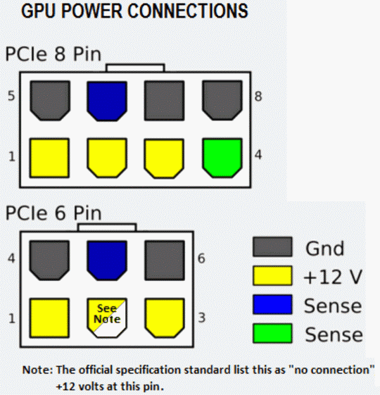
I have an AMD R9 280x PowerColor (never overclocked it) wich was working fine until one day something weird happened. I was watching movies all night and in the morning i left my BSPlayer on pause cuz i had to go to work. When i came back i decided i'd like to do some gaming so i rebooted my PC for optimal performance and then the strange thing happened. I got "No signal" to monitor. I was shocked and i took the GPU out (at that point i was sure its not the monitor, brand new JVC 32"). So i looked at the GPU to inspect for any visible damage, didnt find anything. Tried the DVI slot and different cables (HDMI/DVI), no luck. I got really sad and decided to re-heat the 8 and 6 pin soldering points no idea why, but it worked. 3-4 days later the same problem occured. I decided to take down the passive cooling/radiator and check the termal paste. It looked fine (greasy and not like mud/dust), anyways its not so expensive so i've replaced it with a brand new one. No luck. Then i tried re-heating the HDMI port soldering points (made sure i dont bridge them ofcourse, tested with DMM also) and poof... it worked, sadly for another 3-4 days. I took the GPU down for visual inspection again and i noticed that one side of a tiny SMD capacitor is hanging in the air. No matter how hard i tried to solder it back it just didnt want to stick back to its original place so i decided to give it a try without it. I was amazed when the GPU suddenly ran just fine, with a little problem - I couldnt restart my PC, every time i did a restart i got "No signal", the proper way was to shut down the PC, turn the PWR swich off and hold PWR button for 10 seconds. After that the PC started just fine and without any problems. I was going like this for a month or so until one day i tried to turn my PC on, pushed the PWR button, but nothing happened. No CPU fan spin-up, no GPU fan spin-up, no sound, nothing. I thought that its the damn power connectors (8 and 6 pin ones). Took my DMM, did some (unclear) tests and figured that 2 of the "legs" on those connectors are "shaking". I went to 3 shops to ask if they got 6/8 pin female connectors... No luck they had none, so i decided to try and solder the shaky legs directly to their "planes" (pictures). Well, no luck. So my guess is that i didnt solder them to the right place ?I've tried looking up for schematics, altho i cant really read one, but i couldnt find one eighter... My question is, where exactly do i have to solder them to ?

Please don't say "just buy a new GPU/throw it in the thrash/don't waste your time", i am currently unemployed and that GPU is a gift from my brother and has a sentimental value to me. Plus i've got the time and nerve to tinker with it, hopefully to a good end. Any other ideas are very very much welcome! I'm sure its not a hard task for a guy with the correct knowledge! So please share your thoughts with me! Thanks in advance!

https://ibb.co/1bbVvMz
https://ibb.co/PFFnVKc
 
Solution
Wow, it makes my eyes bleed...

  1. The wires that you have used are too thin for the current, there will be a voltage drop on them and they will get hot if the card works. Very hot.
  2. To remove a short, clean the area properly with lots of flux and mopping the solder away. It looks like solder excess is shorting the board layers, but hard to tell for sure. If that does not help - you have ruined the PCB (by using a Dremel earlier and ripping the pad off even earlier). Or, it may be the sense logic element is bad and causing the short. Or both.
  3. Do not use this spot anymore. To make a workaround - find where this sense line is going to (the logic element) and bridge it with another grounding line from there. It should not be a...
OK, so the card is usually put together with lead alloy at the factory, and it is a pain to take large things off. Besides, those lines on the PCB are copper and they are big chunks of copper foil that take a fair amount of heat.
  • When I take things like that off, I use to pre-heat the card to 100C (on the pre-heater) and only then work on it. If you neglect to do that - you will likely rip the pads off the board.
  • You do not need to apply any force - when the stuff is melted - it comes off easy.
  • 400C is dangerously high, use 350 at the most or some things (like electrolytic capacitors) will start exploding.
  • Once those connector remains are out, clean the area by soaking excessive soldering. DO not use any abrasives. Those exposed layers have to be disconnected from each other when you finish.
SO far we are only undoing what was already done, the real job is still ahead.
 
Last edited:
OK, so the card is usually put together with lead alloy at the factory, and it is a pain to take large things off. Besides, those lines on the PCB are copper and they are big chunks of copper foil that take a fair amount of heat. When I take things like that off, I use to pre-heat the card to 100C (on the pre-heater) and only then work on it. If you neglect to do that - you will likely rip the pads off the board. 400C is dangerously high, use 350 at the most or some things (like electrolytic capacitors) will start exploding.

Sadly i don't have a pre-heater 🙁 I've read that those VIA's on the pins contain something like tiny heat sink (the copper foil you're talking about?) I guess thats why its pain in the ass to remove them... I managed to pull 2 off without damaging the copper panes (total 4 pins out for now). I think ill switch to the skinny needle-like end of my soldering iron instead the big-ass one. I still cant figure how the hell did the first 2 pins got out... i clearly remember that i didnt use any force back then... just heated the soldering point of the pin and poof... it fell by itself super-easy O_O
 
Sadly i don't have a pre-heater 🙁 I've read that those VIA's on the pins contain something like tiny heat sink (the copper foil you're talking about?) I guess thats why its pain in the ass to remove them... I managed to pull 2 off without damaging the copper panes (total 4 pins out for now). I think ill switch to the skinny needle-like end of my soldering iron instead the big-ass one. I still cant figure how the hell did the first 2 pins got out... i clearly remember that i didnt use any force back then... just heated the soldering point of the pin and poof... it fell by itself super-easy O_O
You do not need a needle-like soldering tip, you need a narrow-nose rework gun, or a large tip and patience.
The +12v and the sense pins come off easier than the grounding ones due to the underlying pad being smaller in size.
 
vov4ik_il should i remove all pin's or just the 8 pin ones (PC turns on with the 6 pin connector plugged in) ? No problem, ill take them all if you say i must.
You need to get those new regardless. 8P and 6P.
I just want to make sure that there is no more mess around them.

P.S Forgot to mention the obvious, you should use a static strap and mat, this stuff is ESD sensitive.
 
It was done on a Sapphire Pulse RX570, not the same card, however, the power connector pinout should be the same.
It should be everywhere, it is a standard. It would be wonderful to have a working card with the same layout for diagnostics though... the sense wire usually rings to ground on the PSU side but not always ring on the card, which has to "sense" the connection.
PCIe_pinout.png
 
Still trying to pull those bastards out, i'm not giving up. vov4ik_il i find it almost impossible to find those connectors in my country (Bulgaria). Is it possible to create some other type of connection ? Or perhaps split a spare 24pin into 8 and 6 pins, just a wild thought ? I don't usually shop online since the delivery time is huge... :| If there's no other way i suppose i could try ordering, but i'd really love it if theres a way to bypass the 8p/6p connectors... :|
 
Still trying to pull those bastards out, i'm not giving up. vov4ik_il i find it almost impossible to find those connectors in my country (Bulgaria). Is it possible to create some other type of connection ? Or perhaps split a spare 24pin into 8 and 6 pins, just a wild thought ? I don't usually shop online since the delivery time is huge... :| If there's no other way i suppose i could try ordering, but i'd really love it if theres a way to bypass the 8p/6p connectors... :|
Well, as mentioned earlier, your best option is to get it to a tech that deals with electronics. He might have those connectors and parts from another dead card.

You sure can create a Frankenstein card with wires in place of those connectors, but if we find out that there is anything wrong with the other board components (usually ceramic capacitors or MOSFETs get shot and cause the impulse drivers to die too). Which in turn causes a short on the card and burns all around the power circuitry if there are no input fuses on the board.

Do you think you are capable of replacing one of those? Do you have the tools?
They are much harder to get and replace than those power connectors.
Free-shipping-IRF8327-IRF8327STRPBF-IR8327-10pcs-lot-100-NEW-and-ORIGINAL.jpg
bk9pN7b.jpg

Before you go too far, evaluate your capabilities.
 
Well, as mentioned earlier, your best option is to get it to a tech that deals with electronics. He might have those connectors and parts from another dead card.

You sure can create a Frankenstein card with wires in place of those connectors, but if we find out that there is anything wrong with the other board components (usually ceramic capacitors or MOSFETs get shot and cause the impulse drivers to die too). Which in turn causes a short on the card and burns all around the power circuitry if there are no input fuses on the board.

Do you think you are capable of replacing one of those? Do you have the tools?
They are much harder to get and replace than those power connectors.

Hm can any of those be measured by DMM ? I've been told by electronics tech (no idea if its true or not) that MOSFETs, Memory chips and the Black Boxes (R12, R15, R17) don't "just burn out", no idea what he ment exactly (maybe they are really durable?). You're right i got no tools (hot air gun? pre-heater?) to do such a fix, let alone find those parts if needed, but judging by how the GPU stopped working (PC wont turn on at all, no power AT ALL) makes me think that those parts are still alive...? Again, can those be measured by DMM ?

P.S. My theory is that the PSU "found out" that something is wrong with 8p connector and cut all power (to CPU/GPU/MB) ?
The MOSFETs can be checked with DMM but they have to be off the board for that. You can (usually) narrow down to only those phases that are short by DMM too.
The PWM drivers can be checked with oscilloscope. They get “shocked” by 12v coming the other way from the shot MOSFETs.
Those components are durable until they brake. The short circuit is indeed there and it apparently trips the PSU.
 
Okay both of you guys are much more competent than me (obviously), if any of those mentioned parts burn out, the PC would start (CPU/GPU fans would spin), but i will get "No-signal" or artefacts or some other problem right ? Well last time i used that GPU i didnt had any of those, all of sudden "No power". Whats the chance that something would short out without having power runing through it ? :|
 
Depends on the way they burned out.

If they went open circuit, its possible the pc would still have fan spin and lights.

If they went short circuit your psu would trip a protection and cut power. If a protection did not trip it could cause overheating resulting in melted wires, burned components, tripped circuit breaker in your house, and many other bad things.
 
Guys you're not helping now 😀 Im still alive, no burn marks on the GPU and my house is not lit on fire, cmon show some faith in your БРАТАН БЛЯЕТ!
So far so good:

P.S. In half an hour the shops/repair shops start opening, i think ill go out seeking those connectors and chill my nerves, bloody hard to pull-out those little piss-ass pins. 2 hours for 6 pins... I really need to take a breather lol I hope i can find those connectors and when i get back home ill pull-out the other pins, clean the spot really good and install the new connectors, BUT the question remains... connect wich pin to wich "copper pane" ? I guess after i clean the spot i'll post another picture showing the different "copper panes" around those 8p/6p!

NuZgSU1.jpg
 
Last edited:
Guys you're not helping now 😀 Im still alive, no burn marks on the GPU and my house is not lit on fire, cmon show some faith in your БРАТАН БЛЯЕТ!
So far so good:

NuZgSU1.jpg
Well, it looks like you are committed.
Don’t get me wrong, I am just trying to prevent further damage and frustration.

The plan is (after everything is clean and neat on those power inputs) is to find out which input is shorted and further trace it to the source.
Then all related components will get replaced. Then, after all the inputs are short-free and all power phases are in working order the card needs to get tested on a bench.
If everything works, it can get the power input pads fixed and new power headers.

I am having hard times getting you to do all this with barely any tools and no experience.
 
Sorry it took me that long to respond. I've taken time to go around PC services to ask if they had 8/6p connectors, but with no luck... One of the tech told me an idea, "wire the pins directly to the PSU pwr cable". So heres what i did, my question is, if done right theoretically this should work right? And another question - can i seal with silicone for durability?

 
Wow, it makes my eyes bleed...

  1. The wires that you have used are too thin for the current, there will be a voltage drop on them and they will get hot if the card works. Very hot.
  2. To remove a short, clean the area properly with lots of flux and mopping the solder away. It looks like solder excess is shorting the board layers, but hard to tell for sure. If that does not help - you have ruined the PCB (by using a Dremel earlier and ripping the pad off even earlier). Or, it may be the sense logic element is bad and causing the short. Or both.
  3. Do not use this spot anymore. To make a workaround - find where this sense line is going to (the logic element) and bridge it with another grounding line from there. It should not be a high current line so even 28awg wire should be enough.
  4. On the PSU side, it all looks flimsy. - Get PCIe 8 pin extenders, cut the female pin part and leave the part that goes to the PSU, and solder that to the card or you will have a flash at some point.
  5. Silicon will not add any durability, but epoxy will. It is a bad deal to start with so you will not make it worse by adding some insulation. Only use epoxy when everything is up and running, it is very hard to dissolve it.
The reason it got hot is still there and it will find its way out in a different place if this one will be strong enough to hold it.
 
  • Like
Reactions: fiRe_p0weR
Solution
Hello again friends, sorry to bring back the thread, but believe i've got a breakthrough! I finally managed to "run" the PC with both 8 pin and 6 pin connectors plugged in! After trying 3 or 4 times without success (when i "plugged" the 8 pin, the PC failed to start), finally today i decided to try again and voila... i changed the soldering to the other side of the PCB (the one without the horrible tears) and managed to finally isolate ANY shorts:


Now the problem is that i get "No signal" on display, that sometimes occured before when the GPU was working, i think i have a slight clue where the problem lies. I'll add an image in a minute (a missing tiny SMD capacitor near the crossfire connectors)! Any ideas how can i properly trace the problem ? 😱 BIG thanks in advance (for those who have faith in me ^^)


The green area is where the SMD capacitor was, i tried replacing it, but i can't solder the upper side (cuz there seems to be no spot to solder to), any workarounds ? :O
 
Last edited:
The green area is where the SMD capacitor was, i tried replacing it, but i can't solder the upper side (cuz there seems to be no spot to solder to), any workarounds ? :O
You knocked the pad off, probably when taking the heatsink off. To get a pad repaired, use a razor blade to clean a small area right above it (not your favorite Dremmel tool) or alternatively, if you can ring where does it go and bring a thin wire from there. Then glue (epoxy) a small piece of foil to where it belongs. It is a microscope job with a lot of precision required. When done, use a coating to protect it.

I doubt that is the reason for the card to not start though.
Measure the tensions on all the chokes when you start it, one (or some) of the power phases are probably down. Post a clear photo of the whole board (both sides) so I can point those. This ones are blurry - hard to read markings.

I strongly discourage you from running the card without a cooler attached (your first photo) - it will not take a minute to totally fry the VRM if you get it loaded without a heatsink attached. It is fine for testing up to UEFI output for a moment but no more than that.

P.S you could also use some insulation on those exposed +12v wires and connectors before it zaps something around it.
 
Last edited:
Status
Not open for further replies.