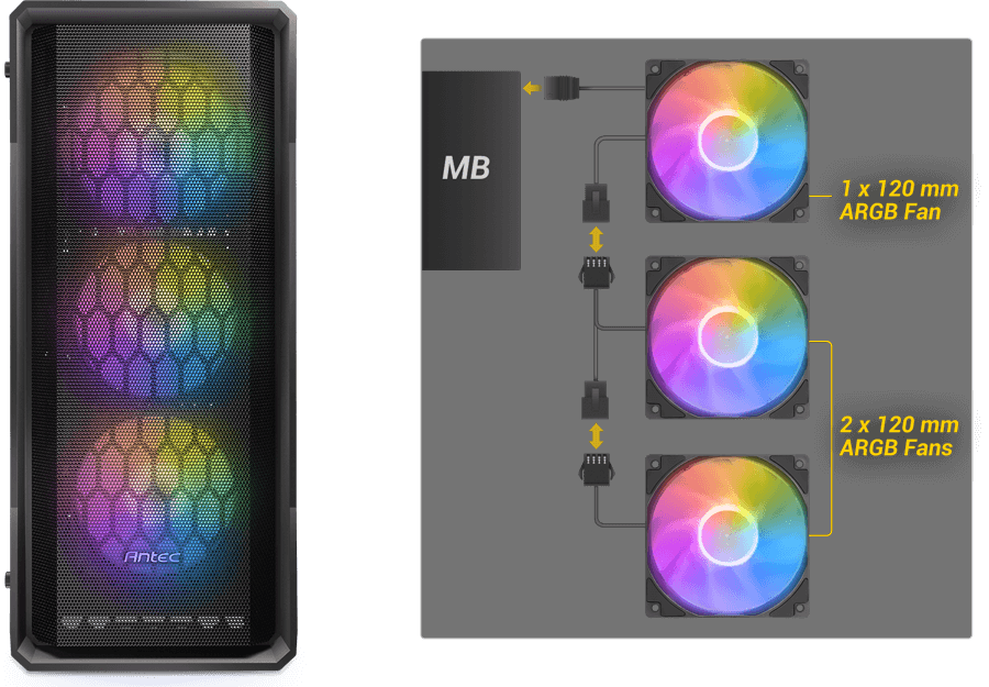
Sorry! You are right, I did not mean to imply stupidity! Your description sound so UNlike any standard set-up I was surprised. Since the case instructions are so poor they say nothing about how the fan MOTORS are powered and controlled. I do note that the diagrams of the fan wiring connections appear to show use of a LOCKING style of 4-contact connector on their cables. The do NOT show a SATA power connector at all!
So, it appears that these fans have ONE cable between each, and one to plug into the mobo ARGB header for the first fan in the daisy chain. THEN on the last FAN ONLY (is that right?) there is that SATA connector in addition to the male output of ARGB. So, the only thing that makes any sense here is that the single cable between fans with 4 wires in it carries ALL of the power / display control lines of ARGB PLUS power for the fan MOTORS. Now, the mobo ARGB header provides signals using THREE lines for the lights and NO power suited for fan motors. BUT it is possible that the 12 VDC power supply for motors is from that SATA connector on the END of the chain, and that power is being fed sort of "backwards" from the end towards the head of the chain. That would only require one line for the +12 VDC supply since the cable already has a Ground line from the ARGB header end.
IF that's how this works, changing it to have the motors' speeds controlled bu a mobo header would be difficult. It would require a custom re-wiring job basically to feed the +12 VDC line of the end SATA connector from Pin #2 of a mobo SYS_FAN header instead of from a SATA power output from the PSU. Then that header would have to be configured to use Voltage Control Mode (aka DC Mode) and base this on the temperature sensor on the mobo, not the one inside the CPU chip. That header would NOT receive any fan SPEED signal so it would want to give you error messages of a failed fan on the header - you might need to find a way to suppress or ignore that error message.
BEFORE doing that, you would need to identify for certain which lines are which in the cables between fans. Of the three lines for LIGHTS, they are:
+5 VDC constant voltage power to lights
Ground
Digital data packets (5 VDC) containing instructions for the display patterns of each LED Node in the fan frame
IF I am correct about this (speculation above) the fourth line in that cable should be +12 VDC when a SATA power source is connected to the END SATA connector.
So, IF that is what you can confirm, you might consider a custom re-wiring job as above.


