Question Antec NX360 front fans and B550-A Pro

Apr 9, 2023
3
0
10
Connectors and motherboard socket

Hi, I've just bought a new case, the Antec NX360 which comes with 3 aRGB fans at the front. They're daisy-chained and meant to connect to the motherboard, however the only connectors (other than the aRGB - which I've plugged into the rainbow1 port) are SATA power and Male 4-pin. Neither of which do I have on my board.

Is there anyway to connect them to my motherboard, so I can actually control them or do I just have to connect them to the PSU and leave them always full on ?

IF it's the latter, is there a better case in a similar design (and price ~£60) that anyone could recommend? 😅
 

Lutfij

Titan
Moderator
Welcome to the forums, newcomer!

According to this image;
nx360-pdt03.png

the fans should de daisychainable. One end seems to be hooked to your motherboard already, which is what I see populating the JRAINDOW1 header at the bottom of the motherboard.
 
Apr 9, 2023
3
0
10
Hi Lutfij,

Yeah...I have seen that image. I have also seen the incredibly useless manual, before anyone says RTFM or something 😅

The only connectors are what's in the pics and the only places to plug into are what show. The fans came pre-daisied. It's literally just that MALE 4 pin and male SATA connection.

They aren't de-daisy-chainable as the connectors and sockets they've wired them with have stupid nubs and aren't actually standard, they've got too much plastic bulk to actually fit the mo-bo heads the right way round.

I think I have unfortunately spaffed money on a useless lemon. Annoying as I'd seen loads of great reviews about the case and fans. Especially for the price point.
 

Paperdoc

Polypheme
Ambassador
Can you read any name or model number on those fans?The Antec pages for that case do not tell us exactly what fans it includes. Their listing of ARGB FANS does not give us anything conclusive except that their fans all are of the common design with separate cables for fan motor and lights.

I agree the diagrams for the case indicate only the wires for the LIGHTS in the fans, and highlight that they can be daisy-chained for that function. This means that the LIGHTING for each fan ought to have TWO cables: one with a female 3-hole connector to go to a mobo header (oar another male output), and the other with a MALE connector (3 pins) to feed power to the next fan's lights. Your post reads like you think the daisy-chain connection is done with ONE cable per fan and then there are two separate left-over connectors, one of which is clearly a SATA power input from a PSU output connector and the other an unexplained 4-pin male. That is not likely.

First question: do you know what a SATA power output connector directly from the PSU looks like? This is NOT on your mobo. It is on the wires coming directly from your PSU. One of those will be plugged into any HDD or optical drive unit to provide power to them. I ask because maybe you mave mis-labelled the connector on your fan that you call a "SATA connector". Does that connector you describe thus have pins, or holes, or just metal contacts on a flat support strip?
 
Apr 9, 2023
3
0
10
Your post reads like you think the daisy-chain connection is done with ONE cable per fan and then there are two separate left-over connectors, one of which is clearly a SATA power input from a PSU output connector and the other an unexplained 4-pin male. That is not likely.


First question: do you know what a SATA power output connector directly from the PSU looks like? This is NOT on your mobo. It is on the wires coming directly from your PSU. One of those will be plugged into any HDD or optical drive unit to provide power to them. I ask because maybe you mave mis-labelled the connector on your fan that you call a "SATA connector". Does that connector you describe thus have pins, or holes, or just metal contacts on a flat support strip?

Hey,

Yes that is EXACTLY how these fans are wired. 4-pin daisy-chained from 1-2-3 ending in those 2 connectors. 1 MALE 4-pin and 1 MALE SATA terminator.

I'm quite certain it is a SATA cable termination. I am and have been a Sys Admin for over a decade, I've fixed my fair share of desktop computers.

If you were to view the pictures linked, you'd see it.

I have however managed to find, from the US Amazon page, that this is a very common occurrence. These case's fans almost always have to be plugged in to a SATA from the PSU. Guess that's the breaks with it being a cheap case. Might get to control the colours but they f**k you over with the fan speed control.

Cheers and thanks for possibly implying I'm some kind of stupid. Sure you didn't intend to.
 

Paperdoc

Polypheme
Ambassador
Sorry! You are right, I did not mean to imply stupidity! Your description sound so UNlike any standard set-up I was surprised. Since the case instructions are so poor they say nothing about how the fan MOTORS are powered and controlled. I do note that the diagrams of the fan wiring connections appear to show use of a LOCKING style of 4-contact connector on their cables. The do NOT show a SATA power connector at all!

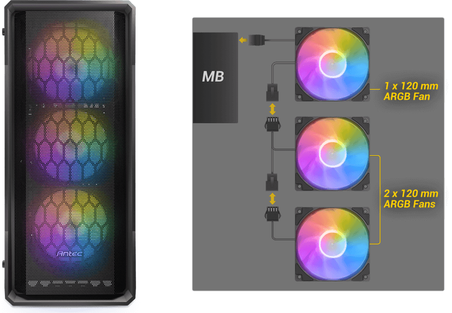
So, it appears that these fans have ONE cable between each, and one to plug into the mobo ARGB header for the first fan in the daisy chain. THEN on the last FAN ONLY (is that right?) there is that SATA connector in addition to the male output of ARGB. So, the only thing that makes any sense here is that the single cable between fans with 4 wires in it carries ALL of the power / display control lines of ARGB PLUS power for the fan MOTORS. Now, the mobo ARGB header provides signals using THREE lines for the lights and NO power suited for fan motors. BUT it is possible that the 12 VDC power supply for motors is from that SATA connector on the END of the chain, and that power is being fed sort of "backwards" from the end towards the head of the chain. That would only require one line for the +12 VDC supply since the cable already has a Ground line from the ARGB header end.

IF that's how this works, changing it to have the motors' speeds controlled bu a mobo header would be difficult. It would require a custom re-wiring job basically to feed the +12 VDC line of the end SATA connector from Pin #2 of a mobo SYS_FAN header instead of from a SATA power output from the PSU. Then that header would have to be configured to use Voltage Control Mode (aka DC Mode) and base this on the temperature sensor on the mobo, not the one inside the CPU chip. That header would NOT receive any fan SPEED signal so it would want to give you error messages of a failed fan on the header - you might need to find a way to suppress or ignore that error message.

BEFORE doing that, you would need to identify for certain which lines are which in the cables between fans. Of the three lines for LIGHTS, they are:
+5 VDC constant voltage power to lights
Ground
Digital data packets (5 VDC) containing instructions for the display patterns of each LED Node in the fan frame

IF I am correct about this (speculation above) the fourth line in that cable should be +12 VDC when a SATA power source is connected to the END SATA connector.

So, IF that is what you can confirm, you might consider a custom re-wiring job as above.
 

TRENDING THREADS