Hi everyone I'm new to pc building. I have an msi b350m gaming pro motherboard and can't completely figure out which way the headers go. The manual is confusing me. Any help would be appreciated!
Front panel connected help
- Thread starter ButteryToastHD
- Start date
You are using an out of date browser. It may not display this or other websites correctly.
You should upgrade or use an alternative browser.
You should upgrade or use an alternative browser.
Solution
No, don't move the HDD LED up (that's for the POWER LED pins you don't have). Use the same pins as before, but make sure the + (gray wire) is at the left and the - (black wire) is at the right.
In short, in your latest photo, you connected the HDD LED here:
[o][o][o][o][x]
[o][o][o][o][o]
^- which is wrong.
You should move it down and connect it here:
[o][o][o][o][x]
[o][o][o][o][o]
Gray Wire (+) at the left; Black Wire (-) at the right
In short, in your latest photo, you connected the HDD LED here:
[o][o][o][o][x]
[o][o][o][o][o]
^- which is wrong.
You should move it down and connect it here:
[o][o][o][o][x]
[o][o][o][o][o]
Gray Wire (+) at the left; Black Wire (-) at the right
Zmanrocks
Distinguished
Im really bad at explaining stuff like this but I will try my best! I recently rebuild my PC because I got a new case. There should be 3 plugs with 2 insert holes each. and 1 that is 2 insert holes but are both split all of these have a place of there own In these slots: (PLED, HD, PWR, and RES) I cant tell you exactly where they all go but the wires should be obviously marked. Also usb plugs go into the usb plug slot and usb 3 has its own special plug
ButteryToastHD :
Hi everyone I'm new to pc building. I have an msi b350m gaming pro motherboard and can't completely figure out which way the headers go. The manual is confusing me. Any help would be appreciated!
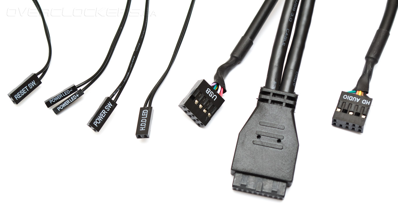
Depending on what your case is, you should have the following basic front panel cables coming out of it:

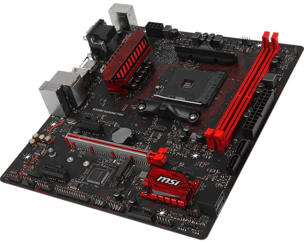
For reference, here is your motherboard:

The first 5 small cables in the photo above, i.e., the "RESET SW" (2-pin), the "POWER LED-" (1-pin), the "POWER LED+" (1-pin), the "POWER SW" (2-pin), and the "H.D.D. LED" (2-pin), will all be connected to your motherboards Front Panel Header (a 9-pin header), which is lablled as "JFP1", found near the bottom-right corner of your motherboard (just beneath the screw mounting hole).
The "JFP1" header, with 9 total pins, is laid out like this:
[o][o][o][o][x]
[o][o][o][o][o]
*where [x] means no pin
You would then plug those 5 small cables this way:
POWER LED + | POWER LED - --> [o][o][o][o][x] <-- POWER SW (+/- orientation doesn't matter)
H.D.D. LED (+ at left; - at right) --> [o][o][o][o][o] <-- RESET SW (+/- orientation doesn't matter)
The last pin (right-most at bottom) is left unplugged.
Next is the mid-sized cable marked "USB" (9-pin). This is used to connect your case's USB2.0 front panel ports. The cable is connected on your motherboard's available USB2.0 internal header. Your motherboard has two of these internal headers, labelled as "JUSB1" and "JUSB2", both are located along the bottom-middle edge of your motherboard. You can choose whichever header you prefer to plug the 9-pin USB cable into. The cable only goes in one way, so, check the orientation of the 9-pin socket against the 9-pin header so you won't break any pins.
The largest of the cables (usually not marked) in the photo above is the USB3.0 (19-pin) cable, used to connect your case's USB3.0 front panel ports. This cable is connected on your motherboard's USB3.0 internal header (also a 19-pin header). Your motherboard only has one, labelled as "JUSB3", located just between the JUSB2 (USB2.0) internal header and the JFP1 (Front Panel) header mentioned above. The cable also only goes in one way, so, check the orientation of the 19-pin socket against the 19-pin header so you won't break any pins.
The last of the cables in the photo above is a mid-sized cable, labelled "HD AUDIO" (9-pin). This is used to connect your case's Audio Jack and Mic Jack. This cable is connected to your motherboard's HD Audio header, labelled as "JAUD1", which is located at the extreme bottom left corner of your board. The cable only goes in one way, so, check the orientation of the 9-pin socket against the 9-pin header so you won't break any pins.
Ok so the case I have only has the hdd led, the power button, and the reset button, where exactly would those go? They're all two pin
ButteryToastHD :
Ok so the case I have only has the hdd led, the power button, and the reset button, where exactly would those go? They're all two pin
Same layout as I have mentioned/illustrated above (just ignore the POWER LED + and POWER LED -):
[strike]POWER LED +[/strike] | [strike]POWER LED -[/strike] --> [o][o][o][o][x] <-- POWER SW (+/- orientation doesn't matter)
H.D.D. LED (+ at left; - at right) --> [o][o][o][o][o] <-- RESET SW (+/- orientation doesn't matter)
The HDD LED + (positive, the gray wire) should be at the other pin (the left-most pin when the motherboard is oriented upright). Flip the HDD LED so that the text would be facing the other way (facing down when the mobo is oriented upright).
No, don't move the HDD LED up (that's for the POWER LED pins you don't have). Use the same pins as before, but make sure the + (gray wire) is at the left and the - (black wire) is at the right.
In short, in your latest photo, you connected the HDD LED here:
[o][o][o][o][x]
[o][o][o][o][o]
^- which is wrong.
You should move it down and connect it here:
[o][o][o][o][x]
[o][o][o][o][o]
Gray Wire (+) at the left; Black Wire (-) at the right
In short, in your latest photo, you connected the HDD LED here:
[o][o][o][o][x]
[o][o][o][o][o]
^- which is wrong.
You should move it down and connect it here:
[o][o][o][o][x]
[o][o][o][o][o]
Gray Wire (+) at the left; Black Wire (-) at the right
vasja.perc
Prominent
raisonjohn :
Yes, just the HDD LED and you're all set 

Wow you explained him so nicely bro, I can not believe how nicely you presented him all the answeres
 . I was just looking at this post, because today I am getting all the computer parts, which will be built in this motherboard, and because its my first time building a pc, I was only afraid of these small pins, I didnt know where to put them. Now i know, thanks to you
Ps sorry for bad English, I'm from EU, Slovenia

TRENDING THREADS
-
-
AMD Ryzen 9 9950X vs Intel Core Ultra 9 285K Faceoff — it isn't even close
- Started by Admin
- Replies: 53
-
Question ASUS Z690 BIOS ver.4301- Not able to use/apply an undervolt offset?
- Started by Shortmoon
- Replies: 2
-
Discussion What's your favourite video game you've been playing?
- Started by amdfangirl
- Replies: 4K
-
Question I have an old system in the basement that has really basic specs, but am planning to give it just a little uplift with an RTX 5060 ti 16gb
- Started by Guy_who_thinks_hes_cool
- Replies: 8
-
Question A scared question but I have to ask ?
- Started by Guy_who_thinks_hes_cool
- Replies: 9

Space.com is part of Future plc, an international media group and leading digital publisher. Visit our corporate site.
© Future Publishing Limited Quay House, The Ambury, Bath BA1 1UA. All rights reserved. England and Wales company registration number 2008885.
