- Mar 19, 2020
- 40
- 0
- 30


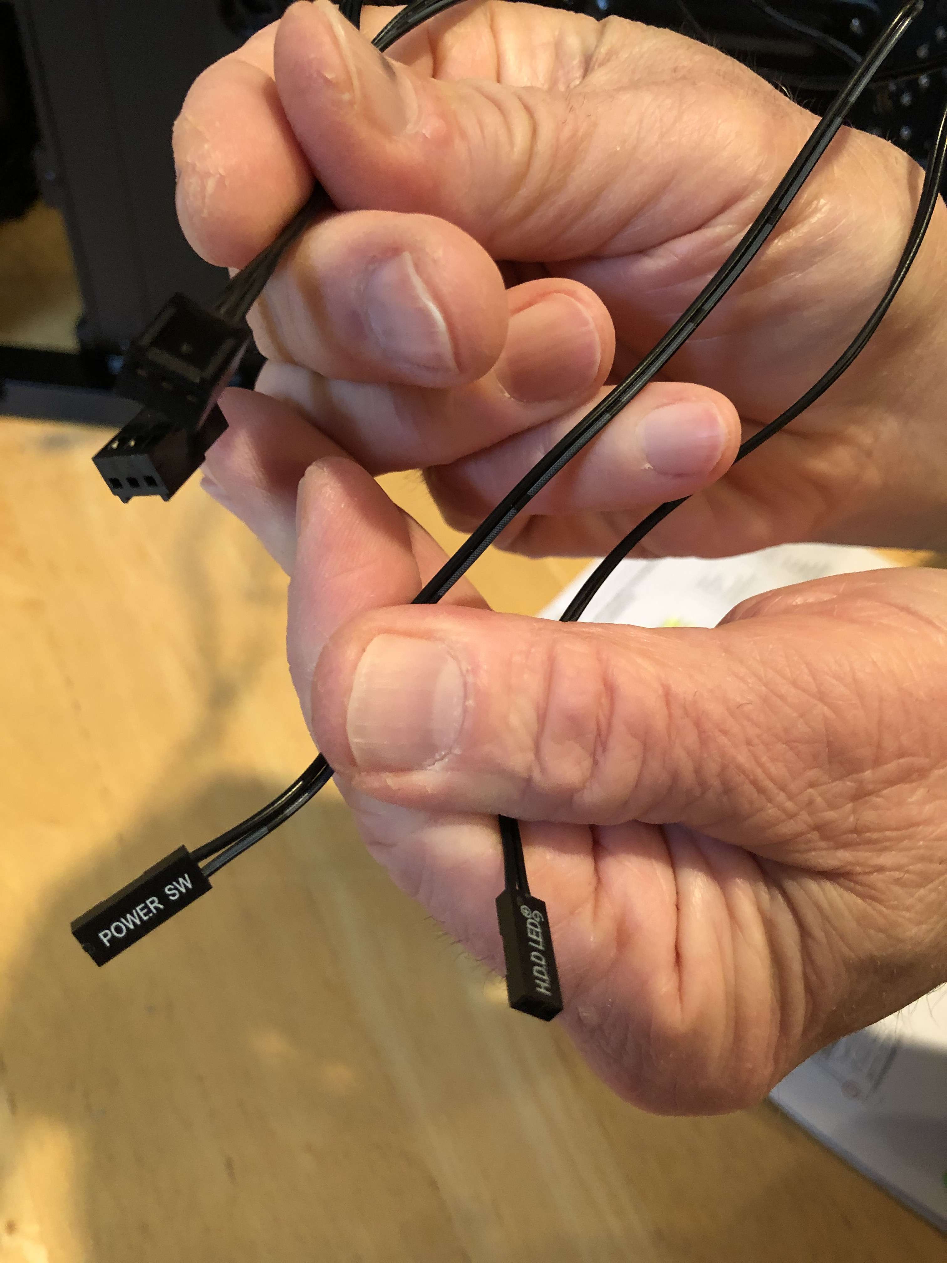
Hello! I am in the process of building an editing pc; however, I am experiencing some issues with the wiring. The case that provides the essential lighting, audio, power, etc has wires that differ from the routing of the motherboard. In the jumper cable for the front panel, I am equipped only with the HDD LED (2 pins) and Power Switch (2 pins). However, there are two additional wires that are both four-pins and their uses are unknown. I have read and compared the motherboard manual with the case for more information, but there are no indicators for the purposes of these two unknown cables. What I do know is, I am missing the Reset Switch and Power LED. I was thinking the wires were somehow interconnected, but I'm not sure how these wires would be plugged in on the motherboard given the front row only contains five pins while the back row only contains four pins total. There's also the issue of aligning the (+) and (-) wires in their respective spots. Is there a possibility the case is different and incompatible with the motherboard? Or, is there a chance I am misinterpreting the uses of the unknown wires and they are meant to be plugged in elsewhere. Help is very much appreciated! More info is provided below:
Phanteks Pro M Series (PH-ES515PTG_BK) Tempered Glass ATX Mid Tower Case, Black
MSI MPG X570 Gaming Plus Motherboard (AMD AM4, PCIe 4.0, DDR4, SATA 6Gb/s, M.2, USB 3.2 Gen 2, HDMI, ATX)
Phanteks Pro M Series (PH-ES515PTG_BK) Tempered Glass ATX Mid Tower Case, Black
MSI MPG X570 Gaming Plus Motherboard (AMD AM4, PCIe 4.0, DDR4, SATA 6Gb/s, M.2, USB 3.2 Gen 2, HDMI, ATX)