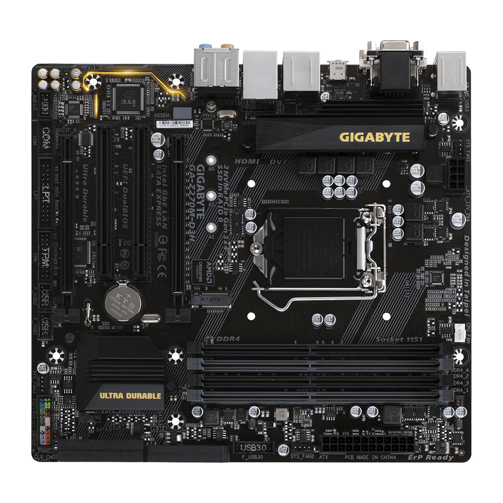
Question Gigabyte MB front pins question

mrblint

Distinguished
Dec 29, 2011
50
0
18,540
I am building a system with a Gigabyte GA-Z270M MB and since this is only the second time I've ever built a PC, the last one being an ASUS about five years ago, I'm confused by the documentation for the pins for the front panel.

The docs say (p.15)

PWR_LED +
PRW_LED -
PWR_LED -

Why are there two negative pins for PWR_LED, and if I have only one such negative wire, which pin do I choose, if it matters?
 

Lutfij

Titan
Moderator
GA-Z270M-D3H-1.jpg

Ideally you should have the -ve pin that is closest to the +ve pin to be populated and in a pair. The pins you're looking for are towards the far left in your manual and are labelled, PLED, not PWR_LED.
 
one negative pin is for S0 (LED on) (MIDDLE negative PIN)
one negative pin is for S3/S4/S5 (LED off)

Power stateACPI state
Sleep (Modern Standby)S0 low-power idle
SleepS1 S2 S3
HibernateS4
Soft OffS5

PLED/PWR_LED (Power LED, Yellow/Purple):
Connects to the power status indicator on the chassis front panel. The LED is on when the system is operating. The LED is off when the system is in S3/S4 sleep state or powered off (S5).

If you only have a two pin connector then only the Sleep (Modern Standby) will give a reading on the LED.
 
  • Like
Reactions: mrblint