News GPU-Z Now Monitors Your 16-Pin Power Connector on RTX 4090, 4080

D

Deleted member 431422

Guest
Nvidia's hardware is unable to monitor power delivery through the connector? How come the card, with such sophisticated power delivery system, cannot monitor itself.
With the connector heated up to the point of melting plastic there should've been some variance in current or voltage flow. No warning signals?
 

InvalidError

Titan
Moderator
Nvidia's hardware is unable to monitor power delivery through the connector? How come the card, with such sophisticated power delivery system, cannot monitor itself.
With the connector heated up to the point of melting plastic there should've been some variance in current or voltage flow. No warning signals?
All pins are shorted together inside the connector and all pins are shorted together on the PCB, so there is no way to do anything on a per-pin basis without a PCB and connector re-design. At best, there could be an SMD thermistor near the he HPWR connector to measure 12V/GND plane temperature in the area.
 
Nov 19, 2022
2
0
10
All pins are shorted together inside the connector and all pins are shorted together on the PCB, so there is no way to do anything on a per-pin basis without a PCB and connector re-design. At best, there could be an SMD thermistor near the he HPWR connector to measure 12V/GND plane temperature in the area.
 

InvalidError

Titan
Moderator
What nonsense are you talking about all pins shorted together? Do you mean ground plane connection for the earth, because you can possibly make a claim like that for the power rails. Where do you get this drivel from.
I mean the connector itself has a foil bus bar connecting all 12V pins together and all GND pins together while the FE cards at the very least have all 12V pins from the connector directly soldered to the 12V plane, same for the GND pins, which makes it impossible to monitor things on a per-wire/per-pin basis.
 
  • Like
Reactions: TJ Hooker

Wrss

Prominent
Dec 19, 2021
11
10
515
What nonsense are you talking about all pins shorted together? Do you mean ground plane connection for the earth, because you can possibly make a claim like that for the power rails. Where do you get this drivel from.
Adding a thermistor would be the same as adding a SMD monitoring chip, that is the nature of PCB design and why they leave vias holes open, for testing and monitoring. Testing chips are easily added for simple one shot functions, you'd only be correct if you tried to add a boundary test system.
Soon as you mentioned drivel I was reminded that I was reading it...

Adapter teardowns show the 6 current-carrying pins that are 12v are simply shorted with the 12 PCIe plug 12v pins. The other 6 pins that represent ground are similarly shorted. There are 4 additional sense/sideband pins that communicate to the graphics card what power it can draw, if any. These are not data pins; they do not communicate temperature. Unscrupulous adapter manufacturers leave those sense pins in an always-full-power state, while a proper adapter has a small IC that tells the GPU the power budget based on how many PCIe plugs are connected. If there's going to be a thermistor in there, it would be to decide when to tell the GPU to cut off all power.
 

InvalidError

Titan
Moderator
If there's going to be a thermistor in there, it would be to decide when to tell the GPU to cut off all power.
The place it would make the most sense to put a thermistor in would be right next to the row of 12V pins from the HPWR connector on the GPU's PCB since any heat from the pins would get conducted into the PCB's 12V plane running next and under the thermistor. If a pin dissipates enough power to reach 170+C and melt plastic, there should be enough heat conducted down the pin into the PCB to detect an unexpectedly high connector temperature there. Of course, that would require a PCB designed with a thermistor there.
 

TJ Hooker

Titan
Ambassador
Shorting power leads in this ways is simply bad design, and shows they are just paralleling power over multiple lines that are rated less than the 1 or 2 molex leads.... Great job intel
This is how virtually all internal PC power connectors work though. 4/8 pin CPU power connector, 6/8 PCIe power connector, they all have 2-4 12V parallel conductors that are usually shorted together on the motherboard/graphics PCB. The fact that the 12VHPWR adapter additionally shorts them together in the connector itself doesn't seem particularly significant.

And I don't think the spec explicitly calls for the conductors to be shorted in the connector. That's just how the Nvidia adapter was designed. Although, again, I don't think it matters much either way.
 

AkroZ

Commendable
Aug 9, 2021
19
16
1,515
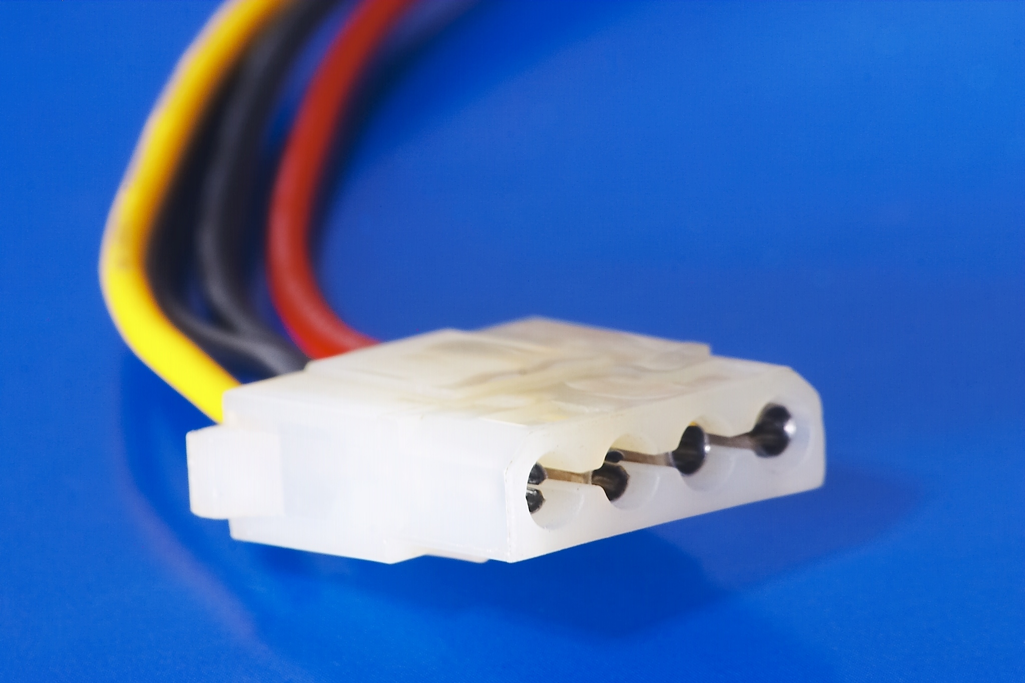
Maybe he is speaking of well known Molex AMP four-pin Mate-n-Lok made in 1963.
Molex_female_connector.jpg

Image and data from Wikipedia.


Pin #ColorFunction
1Yellow+12 V
2BlackGround
3BlackGround
4Red+5 V

Funnily you can read that they have the same issue (arcing), this new connector just make it worse.
Despite its widespread adoption, the connector does have problems. It is difficult to remove because it is held in place by friction instead of a latch, and some poorly constructed connectors may have one or more pins detach from the connector during mating or de-mating. There is also a tendency for the loosely inserted pins on the male connector to skew out of alignment. The female sockets can spread, making the connection imperfect and subject to arcing. Standard practice is to check for any sign of blackening or browning on the white plastic shell, which would indicate the need to replace the arcing connector. In extreme cases the whole connector can melt due to the heat from arcing.
Source: https://en.wikipedia.org/wiki/Molex_connector#Disk_drive
 
Last edited:
All pins are shorted together inside the connector and all pins are shorted together on the PCB, so there is no way to do anything on a per-pin basis without a PCB and connector re-design. At best, there could be an SMD thermistor near the he HPWR connector to measure 12V/GND plane temperature in the area.
Would measuring resistance work? Surely if even one pin is shorting, the resistance will increase - anything over a perscibed level should alert & lower the max power through the connector?
 

TJ Hooker

Titan
Ambassador
The difference is, the old power supplies worked with Pure AC, and didn't deal with PWM power, and the difference is massive. Pushing down Signals that are continuous on to a line rather than simulated PWM means that though the average power are the same, the peaks of PWM are considerably higher, and this has a cost. Shorting power in the supply so that different connectors have the same power is nothing new, and this is not the argument, what is the argument is that these leads and connectors are rated for an average power, and that works for RMS controlled sine waves, but PWM are basically forced squarewaves that supply a peak value well above the average, and not in a nice shape. meaning that the short Bursts (like Digital) actually draw high peaks of power but for short controlled bursts. Fine when its based on signals in the core of a cpu, when the coltages are kept to 3.3v for signaling, but power draw becomes an issue.

Am I talking to someone that is even understanding anything about signalling and power at Frequency. All I am getting is answers that just say "this has been used before!" But its not the same thing or for the same purpose.
Intel are trying to push on people its PWM power systems, and trying to get people to install them on the motherboard. Essentially to shrink down the size of the power supply system, and avoid using large capacitors to remove wasted ripple. But these compromises always come at a price.
The whole point in having multiphase signaling on the Motherboards, was to stop the use of overdrive power used for digital signaling and create Square waves using combinations of multiple sinewaves added together. This ups efficiency, and causes less stress on high power components. Intels tech, does the opposite, and makes it harder, but continually having to change the PWM frequency to match demand. So rather than produce a nice sinewave, polyphase system, which they have perfected on the motherboards, intel wishes to save space, and bend the principles of electronics to use Switching power signals to provide average power.
Sine wave system created individual sinewaves per line and combined them before use. Intels tech just forces the same PWM signals through all lines.Its becomes an issue when the adapter is designed and used on average power, when given that PWM works as a max of 50% duty cycle, has to then provide more voltage at its high state, to average to the designed voltage it needs to feed. So 5v systems, need a 10v supply Minimum at 50% duty Meaning peak values are twice the rated by design...
So what happens when power draw is Maxed, the voltage is 10v for 50% of the time, and though that averages at 5v, it puts possibly more voltage on the devices that are rated for far lower. Current Draw is on demand, so when this increases, peaks of power draw are 0.6x higher that the x Root 2 that it was before.
So different lines all being shorted, means all devices that are shorted to the same connector, or different parts of the system all connected together are subjected to these same spikes of voltage.
My Guess is that the Power adapter meltdown is with high sustained use. If it was simply not connecting the card up correctly, then this would void any warrantee and liability for Nvidia, and they could refuse to replace anything. Or on the other hand, the uses tried to overclock their cards and pushed the power, which is up to its limits, over the threshold.
It doesn't matter if the Transistors on the board can take the voltage, what matters is that any system is as strong as its weakest rated part, and this is the connector system.
Virtually all internal PC power has been PWM-based for decades, so everything you say about Intel trying to push PWM makes no sense. The PSU outputs DC power, there are no "nice sinewaves" anywhere past that point. The only recent change Intel is pushing is to get rid of the minor rails in the PSU (moving them to the motherboard if required). Nothing is changing in terms of CPU VRMs, GPU VRMs, etc. And square waves are not being conducted down the power connectors, they are filtered out by the PSU. The ATX standard mandates that all PSU voltage outputs must remain within 5 or 10% of the nominal (plus 10% ripple), and good PSUs do much better than that. Implying that voltages on the connectors would be twice the nominal voltage of the rail is ridiculous. And even if the voltage were higher, that would actually decrease the current drawn by, for example, the GPU VRMs (so long as the voltage wasn't so high as to damage them). So having a higher voltage would be easier for the connectors to handle, as they would have provide less current for a given power load demanded by the graphics card (hence the 48VHPWR connector for high powered data center applications).

I fail to see how shorting the 12V pins of the 12VHPWR connector (or any connector), would have any impact on ripple/transients being propagated to other devices. As I said before, they all get shorted once they get to the motherboard/graphics card PCB/etc. anyway.

You're really reminding me of another user, @ginthegit. Similar name, similar pseudo-technical comments that use a bunch of EE terms in ways that don't make sense, similar bizarre criticism of PWM voltage regulators.
 

TJ Hooker

Titan
Ambassador
Would measuring resistance work? Surely if even one pin is shorting, the resistance will increase - anything over a perscibed level should alert & lower the max power through the connector?
No, having the 12V pins shorted within the connector would not increase resistance. Plus there is no way for the graphics card to measure the connector resistance with the current implementation anyway.