Hi everyone, anyone
I've got an 8Tb Seagate Barracuda drive here that came in an external enclosure. I was cleaning my office and unplugged everything then when plugging it all back in I accidentally plugged in a higher voltage plug and it has stopped working (no spin-up, no blinking light, nothing). I purchased a new enclosure, tore the drive out of the enclosure it came in and put it in the new enclosure. No dice (just a blinking light on that enclosure). From what I've been reading it's highly likely its either the 12V TVS Diode or a Zero Ohm resistor. I'm sure it could be something else but my gut tells me it's the 12V diode (since it makes sense it would blow when being hit with the 24V accidental plug). I'd like to snip and or blob it and see what happens (like I've read is occasionally possible). The content of the drive is not incredibly important as I do have other backups of the important data on it but I'd like to retrieve what I can, if I can. I have managed to remove the PCB from the drive to try and determine what parts are what and, well, that's where I am now and why I have come to ask for some help. I have included some photos for your reference, I haven't marked them up in any way.
I have also included the part number for the PCB from the "bottom" of the PCB and have a secondary question about this. I have found a site (referenced elsewhere at Tom's Hardware) where I can get a replacement PCB for this drive but the number does not match even thought it is for the same model number HDD. My question is since the PCB is for the same model number HDD but doesn't match the part number for the PCB it came with, is it possible it could still work for me? I understand I'd have to switch out the one chip that seems to be matched with my particular HDD. The part I have found is here: https://www.hdd-parts.com/19062403.html . You'll see it "looks" very similar. I looked closely and there are some differences. I wonder if with the swapping of the certain chip if this would do the trick.
Here are the photos:


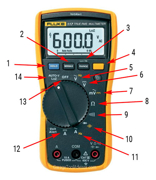
I will admit that I have not checked anything with a multimeter, I do have one but not the skills to use it. I will be doing some reading up on that right away to gain some of those basic skills. Thank you for any help given.
Frazer
I've got an 8Tb Seagate Barracuda drive here that came in an external enclosure. I was cleaning my office and unplugged everything then when plugging it all back in I accidentally plugged in a higher voltage plug and it has stopped working (no spin-up, no blinking light, nothing). I purchased a new enclosure, tore the drive out of the enclosure it came in and put it in the new enclosure. No dice (just a blinking light on that enclosure). From what I've been reading it's highly likely its either the 12V TVS Diode or a Zero Ohm resistor. I'm sure it could be something else but my gut tells me it's the 12V diode (since it makes sense it would blow when being hit with the 24V accidental plug). I'd like to snip and or blob it and see what happens (like I've read is occasionally possible). The content of the drive is not incredibly important as I do have other backups of the important data on it but I'd like to retrieve what I can, if I can. I have managed to remove the PCB from the drive to try and determine what parts are what and, well, that's where I am now and why I have come to ask for some help. I have included some photos for your reference, I haven't marked them up in any way.
I have also included the part number for the PCB from the "bottom" of the PCB and have a secondary question about this. I have found a site (referenced elsewhere at Tom's Hardware) where I can get a replacement PCB for this drive but the number does not match even thought it is for the same model number HDD. My question is since the PCB is for the same model number HDD but doesn't match the part number for the PCB it came with, is it possible it could still work for me? I understand I'd have to switch out the one chip that seems to be matched with my particular HDD. The part I have found is here: https://www.hdd-parts.com/19062403.html . You'll see it "looks" very similar. I looked closely and there are some differences. I wonder if with the swapping of the certain chip if this would do the trick.
Here are the photos:


I will admit that I have not checked anything with a multimeter, I do have one but not the skills to use it. I will be doing some reading up on that right away to gain some of those basic skills. Thank you for any help given.
Frazer


