Question LAN Cable passes test but won't work

Jan 2, 2020
38
4
35
Apologies in advance for the length of this post, I've tried to keep it brief but there's a lot to tell. I'm feeling like I've just hit my skill limit, so all help appreciated!

I've previously run various LAN cables in the house via the loft, all fed from keystones in a patch panel in a little 10" rack together with a switch. I'm having problems with this latest one though. I consider myself reasonably competent, although I'm definitely not very experienced with LAN cabling.

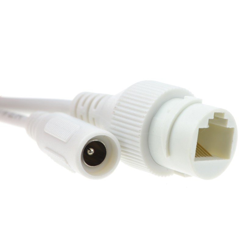
The slightly weird thing is that this is for a CCTV camera on the underside of the soffit, fed from the loft, so it needs a dangling plug instead of a wall socket. I did consider putting a socket in the loft above and a patch cable from there to the camera but this would mean there was an unsealed connection in the loft that would get dirty and/or damp. The camera comes with a nice waterproof hood that seals its connection to a plug, so there won't be any exposed connections this way.

So, this meant I had to buy a crimp tool and fit a plug for the first time, directly onto the end of the cable that's fed from the switch. I bought a hopefully decent crimp tool and some plugs. After making a practice patch cable that seemed to work*, I put the plug onto the proper cable ready for the camera. I then tested it end-to-end using one of those cheapie testers that lights 1 of 8 LEDs at each end in turn. This showed all OK, counting 1-8 at each end with no missing or crossed connections.

Then, I plugged in my camera and... nothing. This is a POE camera, so to remove that complication I even tried using the optional separate DC adaptor and standard switch instead of the POE one, again nothing. I then tried plugging in my wifi access point via a coupler in place of the camera, again nothing - no LED on the router, completely dead.

I've also tried cutting off and replacing the plug and keystone at each end, I even re-laid a new length of cable. Still nothing works.

I buzzed out my plug that I chopped off with a DMM and it is definitely connected correctly with no crossed connections, near enough zero ohms on all connections (the same as touching the probes together), all looks very healthy as far as I can tell.

I've wired both ends according to the 'B' wiring code.

I've used the same keystone and Cat6a cable as elsewhere, with no issues before, although it is a new reel so I can't rule out that it may be a one-off dud.

* The practice patch cable that I made first previously did work but, after a wiggle, doesn't any more. This is pointing the finger at the plugs.

I've ordered some different plugs. It's quite thick 23awg solid core cable so I got the plugs that have staggered crimps to fit them all in. The ones I've ordered use a different layout to achieve this, so are definitely different.

Also, I can confirm that if I connect the camera directly to the switch it works perfectly, with either the standard or POE switch, using the same patch cable I was using between the switch and patch panel. The problem is definitely between the keystone and the plug at the other end of the new cable. It's about 15m long, I already have longer runs elsewhere so hopefully the length isn't an issue.

Firstly, is it wired correctly, or do I need some kind of reversal or crossover due to the fact that one end is a plug rather than a socket?

Is it even OK to fit a plug onto solid core cable as I have done, or is stranded required?

How likely is it that a cable can pass a continuity test but fail in actual usage? I realise that running at 100MHz or gigabit is much more demanding than DC, possibly capacitive coupling effects could be going on.

All hand-holding very much appreciated, I've got that feeling I've just waded a bit beyond my depth here.
 

kanewolf

Titan
Moderator
Is this 100% copper wire or did you get CCA (copper coated aluminum) ? The resistance of CCA would be much higher than copper and that could impact POE.
There are two POE standards 24V passive POE and 48V 802.3 POE. You do need to be sure your POE source and POE device use the same standard. Switches are usually 48V. A device specific injector could be any voltage.
 
Jan 2, 2020
38
4
35
Hello, thanks for the input.

I've pretty much removed the PoE aspect from the issue, as I've been testing using its own DC supply while things are in doubt. I've also tried out a wifi access point in its place that doesn't work either. All this testing was done connected to the standard switch, not the separate PoE switch.

Also, if I connect the camera directly to the PoE switch then the camera and switch light up and it works perfectly, so I'm hopeful I've managed to get a combination that's compatible. But as I say the issue is more fundamental than the PoE issues, it just won't work as a standard LAN connection.

The cable is hopefully very decent. It's this stuff...

https://excel-networking.com/catalogue/product/100-196

I've just checked an offcut to be sure, it's definitely copper coloured all the way through and it does bend, rather than springing back straight as I know alu cable does.

I'm just wondering now whether putting a plug onto solid cable is just a stupid thing that nobody normally does? In which case I probably need to replace it with stranded.
 
Jan 2, 2020
38
4
35
By the way, the cable shield is grounded at the patch panel. The camera doesn't need the shield, its socket is just plastic. I just trimmed back the foil at the point I fitted the plug.
 
Jan 2, 2020
38
4
35
Oh, also the camera will not move once installed. So it doesn't need flexible cable for the sake of allowing movement. Solid core cable would be fine if this is OK electrically.
 
Jan 2, 2020
38
4
35
Aha - there are different types of IDC terminals inside the RJ45 plugs for stranded and/or solid. I need to ensure that the plugs I use are rated not only for 23awg but also for use on solid, some may be for stranded only, something I hadn't thought about. Some info here...

http://www.l-com.com/content/Article.aspx?Type=N&ID=10592

I've just checked, the ones I ordered today are rated for stranded OR solid, but the ones I've used don't state either way. In fact they don't even have a brand name, I bought them pretty carelessly really. It's starting to look more like changing the plug may well be the answer.
 
I think you've nailed it with the solid vs stranded rj45 plugs. I had to re-crimp an rj45 at one of our businesses that just somehow cracked and broke apart over time and it was my first time and it was with solid connectors and I was lucky I got the right plugs. I had to do it 3 times before I got it right, but after that exercise I was able to take some old cable and make some patch cables out of them, so the skill can be handy. :)

Worse case scenario if you can't get it working, just get a pre-terminated cable for the length you need and then use your existing cable as a pull string. Then if it fails it's someone else's cabling, haha.
 
  • Like
Reactions: hackster
Jan 2, 2020
38
4
35
I'm fairly hopeful that I can get the plugs wired OK, the one I pulled apart and tested looks reassuringly neat. I was very careful to get all the cores totally straight and ensured I could see all 8 wire tips through the end of the plug before crimping.

I don't think I could get away with a pre-made cable, as it needs feeding through some fairly slim holes. I've used a 40mm plastic pipe as a trunking for them all across the length of the loft, and it's starting to get quite full. I have access from each end so this keeps them neat and safe, plus avoids me needing to crawl across the length of the building. I just use an electricians rodding set to feed each one through.

I'm pretty sure the issue is that the crimp is basically a pointy tip prodded into the side of a solid rod of wire. Basically, it's only connecting via the equivalent of a fingertip, whereas the right sort of crimp would squeeze the wire between the sides of two springy fingers. This would explain why it has reasonably low DC resistance but is useless at MHz signals.

I'm a bit concerned about just how little space there is inside an RJ45 plug though. Clearly they're not the sort of plug anyone would design from scratch to be used with 23awg cable, the fact that the cores need to be overlaid just to fit in is really a bit of a botch. Basically, the 8 cables side-by-side are wider than the plug. The cable size has been increased over the spec revisions, to the point that it won't fit in the plug any more.

The ones I got previously went in like this...

O-O-O-O-
-O-O-O-O


The new ones are like this...

OO-OO-OO
--O--O--


But both are really solving a problem that's caused by history. Both need the contacts to reach between the top row to pierce the ones below, and also need the contacts to lean sideways at various angles. If you then have terminals that reach down the edges of the cables then it doesn't leave any clearance space between them, there must be a real risk of them shorting against their neighbours. A wider connector would have been a better idea when Cat6 was invented, it would only have needed a plug-in adaptor for backward compatibility.

The hood that came with the camera is really good, it has a silicone gasket that seals against the cable itself and the socket, so it should be immune from corrosion once it's all together.

I'll update when the new plugs arrive and I try one, either with joy or doom.
 

kanewolf

Titan
Moderator
They guarantee it, and I've dealt with their cables before. They really wouldn't put this out there like this if it wouldn't work.
This is one of those standards things. The standard says it MUST be 22-24. That immediately makes it not a ethernet cable no matter what any company says. It does not matter how much they guarantee something it can does not change the rules to what is and whats is not a ethernet cable.

Will it work who knows you are only taking this companies word for it. They likely know it will not work for some people and feel it worth the costs to ship a different cable. I would really like to see a fluke meter certification report for a 100 meter cable for a cat6a. I bet it can't even pass cat5e at 100 meters.

This fake cable stuff has gotten so bad lately, this is one of those things that it is too bad the group the run the standards does not enforce rules against this fake cable in the courts.
I hear what you're saying about standards, but there is always a way to get the same signal without necessarily meeting the standards--it just usually costs more. If you've dealt with cables, the warranties matter. Garbage cables break down over the years and are useless. The lifetime ones from legit companies typically won't because they WILL have to replace it, which they don't want to do.

Anyone can label a cable with anything, and I could care less what the label says. If they are willing to stand behind their claim in a legit way, then that's all I need.

I'm running gigbit on cable so old wifi wasn't even invented. How did I do that? I made sure it was 400Mhz rated wire at a time when 100Mhz was about all there was. Sure it was 2x as expensive, but it was nothing compared to the overall cable build-out cost. When something is built well, you don't have to worry. Monoprice became the company it is because of their cables--it is their bread and butter and they can't mess it up. ymmv of course.
 
Jan 2, 2020
38
4
35
I agree that the required (thick) cable is vastly preferable. Presumably there's a reason why the boffins that wrote the spec required this, no doubt after lots of modelling and testing. Guaranteeing a cable to work is not the same as guaranteeing its performance. You could probably run gigabit over Cat5 or less and it would appear to work, even without any obvious problems but the reality would be that the network driver software at each end would be continually seeing errors. It may be that the receiver could correct some, and that it would request retransmission of those that were too corrupted to recover.

The end result would be that the end user would see a working connection, although in reality it would be like the swan that's gliding gracefully on the surface but paddling like flip underneath, it would be slower and suffer from random amounts of lag, perhaps with occasional outright failures.

I've bought a load of pre-made patch cables recently. I needed to chop one end off one anyway, to wire it into a socket (weird I know, but it works). It was very useful to be able to check what was inside, thankfully it was a very decent cable so I could confidently order more for everything else. Perhaps if I need to select again in future I may just order an extra just to chop up, whether needed or not.

I saw a lot of "slim" cables that are almost like ribbons. I doubt that the cables are even twisted in these, presumably they're just side-by-side and are also very thin too.
 
Jan 2, 2020
38
4
35
Well, the new "Cat6a" plugs arrived, I was going to try a practice one until I found that the cables won't even fit into the holes. Now I've seen that the spec states maximum 1.1mm cable thickness, I've just checked mine and it's around 1.3mm.

I've just ordered a third contender. Hopefully this will tick all the boxes, 23awg, 1.3mm and solid. If not then it looks like a keystone socket and patch cable may be the remaining option.

IMO Cat6a and beyond RJ45s are a total botch, they should have changed to a bigger connector as the cable diameter was increased.


Standards are there for a reason, as are trained professionals who do this for a living, not being able to do something well doesn't mean anything is botched!!! Purchase the correct cable and correct connector. Then use a proper tester not one that just tests continuity!!!
 
Jan 2, 2020
38
4
35
My apologies if I've accidentally trodden on any toes, obviously I know nothing about cables and connectors being degree qualified in electronics and having spent half a lifetime in the industry.

It's possible that the Excel-branded cable that I happen to have chosen may be a contributory factor, I did see it specifically stated as being unsuitable by the seller of one of the plugs I saw. It does have particularly thick plastic over the copper, which may be a good thing for strength and/or signal integrity, but obviously a right pain for stuffing into a tiny hole. I completely understand that putting a plug onto solid core cable is a bit of an oddity in itself, that's why I haven't needed to fit one before, so why this is a whole new world of annoyance and unexpected complication to me, and others too. It may well be that most 23awg cable is below 1.1mm, but even then it still requires the interleaved cables as I illustrated previously. Which is a botch, due to the fact that the cable is wider than the plug!

I'm fully aware of the difference between DC continuity and a proper live test. That's the point of this thread, which anyone reading beyond the thread title would have been aware of.

It's all too easy to say purchase the correct cable and connector. The thing is, I already have a reel of this cable and it's already installed, along a pretty awkward route. I'd rather not replace it, but I know that getting a plug to suit is going to be tricky. Hopefully I've found one, will have to see when they turn up.

Please feel free to contribute further if you've got anything useful or helpful to anyone to say.
 
23 awg wire I would think would be well below 1mm. The actual wire itself is less than .5mm. You would think the insulation on the conductors would be less than the wire itself.

Now if you mean the thickness of the cable itself where it crimps into the back of the jack. That is the major issue with using any form of shielded cable. Shielded cable is rarely used anywhere because of the difficulty installing it correctly. To be correctly installed it must be grounded on both ends to a ground the is separate from the electrical ground. The only place you find these type of ground connections is in large data centers.

Even in these installs they only use it between patch panels. To get a proper ground on the equipment end the equipment needs a special tab on the sides of the jack that will make contact with a special metal rj45 plug on the cable. This type of ethernet ports are extremely rare. So from the equipment to the patch panel they use non shielded cable because it serves no purpose if it is not properly grounded.

In any case they must make rj45 plugs that work on your cable. If the cable is very special you might have to get them from the manufacture of the cable.

Maybe simpler to use a keystone and then a short commercially build ethernet cable.
 
Jan 2, 2020
38
4
35
Hello. The shielding is not the issue, I've been stripping that all back and out of the way. I have been using metal-shelled plugs, but the camera it's connecting to has an all-plastic socket, so the shielding stops at that point anyway.

The shield is grounded at the patch panel, only to electrical earth. I do understand that this isn't a very clean earth, but it's the best I have. I may add a ground rod to the earth at some point, in fact this may be a requirement for some other unrelated work we're doing on the place.

The plastic around the core is the problem, it's really thick. In fact it looks crazy, a lot like a tiny candle, where the copper core is the wick!

I may ask Excel for a recommended plug, although I'd expect that their recommendation would be that this is installation cable, not flexible patch cable, so it would normally be wired to a keystone or socket.

The keystone + patch cable option is the backup plan, in fact it was the original plan and I've already bought some quite neat plastic surface mount boxes that contain a keystone each. The reason I changed plan was that this would leave an unsealed plug/socket connection within the dirty and possibly damp loft space just under the roof tiles. If I can cable directly to the camera then it will be completely sealed, as the cameras are supplied with a really neat sealed boot that encloses the plug and socket completely.

These are pictures of the socket and the plug boot, they have silicone seals at each interface and work really well...

encam-cctv-ip-5mp-36mm-sony-starvis-starlight-dome-camera-grey-090046.jpg


encam-cctv-ip-5mp-36mm-sony-starvis-starlight-dome-camera-grey-090046.jpg


It just seems a shame to add an additional unsealed plug and socket in series with this. The additional DC socket is not needed when using PoE, there's also a seal provided to blank it off.
 
Jan 2, 2020
38
4
35
I'm happy to update to say that I finally found a plug that works perfectly on the end of the Excel cable. I got this, from ComputerStar/Fairline, MPN 9200-750 ...

https://www.ebay.co.uk/itm/392445428875

Not cheap, this is per plug. I had a good look at the terminals with a magnifier before crimping, and I could see the offset tips, designed to straddle around the solid wire. After crimping, I can see that the tips of the copper cores all remain central within the plastic and all looks healthy.

It passed the DC test, and then it just worked when I connected up the camera and PoE switch. Like it should in fact. I had to snap off the extended strain relief crimp, as the special boot supplied with the camera doesn't have space for it. However, this provides strain relief anyway, as well as being completely sealed.

The cable is shielded, and is earthed at the patch panel next to the switch. This would be the end of the line for the shield anyway, as the camera's socket is plastic. It's really not critical whether the plug shell gets earthed in this case, as it doesn't connect onwards to anything anyway. I removed all the foil, then cut the single earth wire to length so that it sits alongside the metal shell but is too short to ever reach the contacts. So it's squeezed between the metal plug shell and the plastic outer boot - hopefully this will earth the shell but it doesn't really matter if not, and it can't ever touch the signal contacts wherever it happens to end up.

The original that I had such trouble with was this one...

https://www.ebay.co.uk/itm/192892570460

After looking at the one I fitted (that passed the DC test) with a magnifier, it's now obvious that it was a complete mess. Clearly the contacts are just pointy and straight, so they just hit the edge of the copper wire, contacting by just a microscopic equivalent of a fingertip. Most of the tips of the copper cores had been pushed way off-centre. Three of them had been pushed right through the plastic coating - there was about 3-4mm of bare copper visible on the opposite side of the cable.

So, got there in the end. Hopefully this might be of some use to anyone else who ends up with the same learning experience.