Question 4PIN aRGB Fans

May 23, 2023
9
0
10
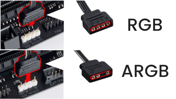
So apparently i got 4 aRGB fans, each fan comes with 4pin PWM connector, out of this connector one pin goes to "IN" on aRGB strip, 2nd goes to "GND" on both fan and strip, third "VCC" or "+5" goes in both in fan and strip and 4th pin which im not confirm if thats PWM wire goes only in the fan...
Now what can i do or buy to connect this fan to 3PIN argb controller as well as PWM hub if this fan does support that
 

Paperdoc

Polypheme
Ambassador
Your fans, like most lighted fans today, probably have TWO cables each. The larger one with THREE holes is for the ARGB lights in the frame and looks like the BOTTOM item in this photo.

oeskf3imqdlcltz60brwpb7v0ie2mgazbi1n8kl6taoqsupx2rbobjg0bqvi762t.png


It plugs into a matching (4-1) header with 3 pins on your mobo IF you have one, or from a separate ARGB Controller.

The second cable has a narrower connector with FOUR holes and ridges down one side. It is for the fan MOTOR and looks like this
4-Pin-Connector.jpg

It plugs into a SYS_FAN or CHA_FAN header on your mobo, or into a fan Splitter or Hub.

Most often any devices to combine several fans' connections into a central unit are SEPARATE - that is, one for fan motors, and another for lights. However, there are some that have BOTH devices in one unit, and you can tell which ports are for which by the pin designs.
 
  • Like
Reactions: DMW888
May 23, 2023
9
0
10
Your fans, like most lighted fans today, probably have TWO cables each. The larger one with THREE holes is for the ARGB lights in the frame and looks like the BOTTOM item in this photo.

oeskf3imqdlcltz60brwpb7v0ie2mgazbi1n8kl6taoqsupx2rbobjg0bqvi762t.png


It plugs into a matching (4-1) header with 3 pins on your mobo IF you have one, or from a separate ARGB Controller.

The second cable has a narrower connector with FOUR holes and ridges down one side. It is for the fan MOTOR and looks like this
4-Pin-Connector.jpg

It plugs into a SYS_FAN or CHA_FAN header on your mobo, or into a fan Splitter or Hub.

Most often any devices to combine several fans' connections into a central unit are SEPARATE - that is, one for fan motors, and another for lights. However, there are some that have BOTH devices in one unit, and you can tell which ports are for which by the pin designs.
Thats the fking bad thing about my fans, I took off the fans and really there is only ONE single wire set, I took of diffuser and got to know, from this wire set 1 wire goes to fans, other wire is GND which went to fans and then to aRGB strip, third is VCC (+5V) which went to fan aswell as the strip and fourth one only went to IN/DATA on strip...
On this case I have four fans daisy chained which these PWM connectors to each other while the rear fan(LAST ONE)'s PWM connector also goes into sata power (Specifically) only 3 out of 4 wires went to SATA...
This rear fan is also giving 2 more cables; 1 which is aRGB connector(3PIN) which 2 pins is only connected to this connector, and another 2pin connector which is attached for LED button on pc case...

I could plug the aRGB connector from rear fan and use it to control all the fan but i want to control each fan individually.
Now i know my ENGLISH might be really bad so ill make sure to try getting a good video showing how all the fans are linked but for a straight answer, ya my fans only have ONE 4pin PWM connector EXCEPT the rear fan
 

Paperdoc

Polypheme
Ambassador
Now I understand better. Your fans are designed with NON-standard connectors between them so they MUST be connected in this daisy chain fashion. Then the entire chain has connections from the "rear fan" to a SATA power output from the PSU plus two cables for other connections. One of those goes to a mobo ARGB header with 3 pins in a (4-1) arrangement, but only two wires are used there. VERY likely those two are the Ground and Digital Control lines. The 5 VDC power supply required for the lights comes from the SATA power connection. That SATA connection also provides the 12 VDC power for fan motors and a Ground. The last cable that goes to a case-mounted button with a label "LED" is just how you can change the light display pattern. This means that the controller for those displays actually is built into the "rear fan" and it generates whatever display pattern you choose using the LED button.

From your description I see no connection to a mobo fan header, so there is no way to control the fan speeds. I expect they all run at full speed all the time since they are fed from a fixed voltage supply line from the SATA power output connector to the PSU.

All of this does not follow any common standard for fans or lights. There is NO simple way to convert those units to use mobo headers for control. Even if you could custom re-wire to mobo headers, it is likely that your fans do not contain some of the electronic components needed to use the mobo signals for control of anything.