Hi,
I have a question. I been try to figure out to control my ARGB fans a into simultaneous blink mode. As most people knows, even you had the most luxury mobo, manufacturers only give 2 headers for ARGB and most of them are 3.0A max.
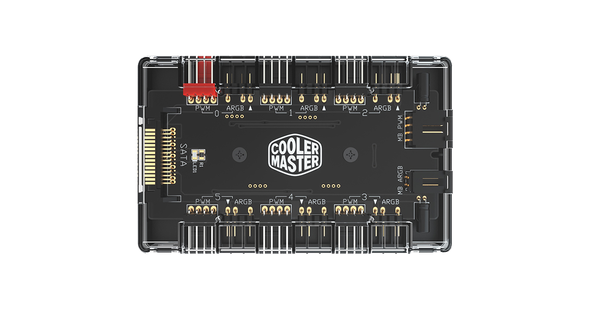
Thus, i begin to plan use the fan hub unit as below:

 www.coolermaster.com
From my understanding, the hub itself has the maximum 4.5A for fan LED current which i don't think the header at the mobo will support it. I am suspecting it drawing current from the SATA power source.
Then, i do see that it only has 2 pins which label MB and ARGB from the fan hub itself in order to link with 5V headers. I also suspecting it only draw D pin which is Digital signal to control the connected fans. If only someone can show me the point routing at the pcb hub.
I just want to be clear. Hoping you guys can help me.
I have a question. I been try to figure out to control my ARGB fans a into simultaneous blink mode. As most people knows, even you had the most luxury mobo, manufacturers only give 2 headers for ARGB and most of them are 3.0A max.
Thus, i begin to plan use the fan hub unit as below:

MasterFan ARGB and PWM HUB
The new MasterFan ARGB and PWM HUB is capable of connecting up to 6 sets of Addressable RGB (3-pin) headers and PWM headers simultaneously. It enables users to expand cooling capability and enjoy greater system performance. Its small and compact design allows you to control your PWM ARGB fans...
From my understanding, the hub itself has the maximum 4.5A for fan LED current which i don't think the header at the mobo will support it. I am suspecting it drawing current from the SATA power source.
Then, i do see that it only has 2 pins which label MB and ARGB from the fan hub itself in order to link with 5V headers. I also suspecting it only draw D pin which is Digital signal to control the connected fans. If only someone can show me the point routing at the pcb hub.
I just want to be clear. Hoping you guys can help me.

