Question RGB Watercooler ML120R RGB on old Mobo (GA-x79-UP4 (rev1.1))

Feb 2, 2024
6
0
10
Hi All,

I have been looking on this great forum, and have found https://forums.tomshardware.com/threads/aio-cooler-on-an-older-mobo.3539222/ and https://forums.tomshardware.com/threads/help-with-rgb-fans.3833243/ , but they don't really provide an answer to my question and the store I bought the watercooler from, doesn't really know...

So I am running unraid on the old hardware from my old desktop pc (only unraid, nothing else). I had a corsair watercooler which broke down and I replaced it with a new watercooler, which is an RGB (Cooler Master, ML120R RGB).

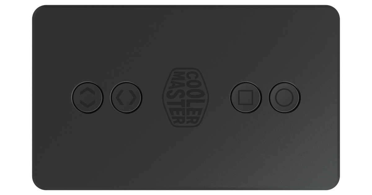
I have everything hooked up as indicated and I think the fans and the pump are doing their job (CPU temp is around 30° normally and goes to around 42° under loads (Plex Server), but the RGB lights do not come on. The Two fans are hooked up via a Y splitter to CPU FAN on the Mobo (both 4 pin) and running, the other two are fed into the RGB remote as indicated in the schematics with another splitter cable. The two cables coming from the CPU cooler/pump itself - 1 is fed into the RGB remote as well, the other is meant to go into CPU_OPT, but since I don't have that on my Mobo, I have put it into SYSFAN4 (both 3 pin). I also connected the USB (USB Header Connector and USB Adapter) to feed power to the RGB Remote.
The cable for Gigabyte Mobo connection to the RGB Remote, I cannot put on my Mobo anywhere (probably my mobo is too old?). It's called the ARGB 3-Pin Motherboard connector.
I don't mind too much that I can't control the RGB lights, but it would be nice that they can just "come on".
Just for reference : I didn't put the cables for Case Restarting Line, or Motherboard Restart wire, since I don't use them anyway.

I have an LGA2011 mobo (Gigabyte GA-x79-UP4 (rev1.1)) and put Thermal Grizzly Kryonaut Thermal Paste on with an Cooler Master MasterLiquid ML120R RGB water cooler.

Is it just not possible, or am I missing something?
 
Welcome to the forums, newcomer!

You can add this to your build;
and get ARGB control on your platform though if the fans work apart from the LED's you shouldn't be worrying about adding another component to the build.
 
  • Like
Reactions: Paperdoc
Start with this: in the lighted fans you have (and the pump unit), the fan MOTOR and the fan LIGHTS are two completely separate "devices" in one unit. Electrically they are independent, so each has its own connector and cable.

I'll deal with the AIO set of motors and cooling system first, lights later. The design of the AIO cooler intends that the PUMP motor always should run full speed, so it requires that power fed from Pin #2 of its mobo header always be the full 12 VDC. All control of CPU cooling is done by the RAD FANS - they are newer 4-pin PWM style fans, and their speed is controlled by the PWM signal they get from their header. That means they need to be connected to a header that uses the temperature sensor inside the CPU chip for guidance, and that always is the CPU_FAN header. IF your mobo had a CPU_OPT header also, that would simply be a copy of CPU_FAN, so using both those is ideal for your system. BUT you do NOT have that, so we need another plan.

There's another important function of the CPU_FAN header. It monitors the speed signal of its "fan", and IF there is NO speed signal it treats that as a FAILURE of the "fan". That triggers an on-screen warning and, in a short time, complete shut-down of the system even without waiting for the temperature inside the CPU to show high. This is to prevent permanent damage to the valuable CPU with NO cooling. Many such systems even will not allow you to start up if the CPU_FAN header gets no speed signal immediately. Now, in an AIO system, the most important item to monitor for failure is the PUMP. No fluid flow means NO heat removal. On the other hand, if the pump is running but one or even both rad fans fail, the result will be a slower temp rise in the CPU chip that will be detected by a separate system and cause other on-screen warnings and slow-downs of the processor before a shut-down. So in your system it is important that the PUMP be connected to the CPU_FAN header for this protection to work.

However, we also want the RAD FANS to be connected to CPU_FAN since that is the only header that DOES use the CPU internal temp sensor for guidance. To accomplish this you need a simple SPLITTER. This is a device with one input "arm" that plugs into the CPU_FAN header, and two or more oputput "arms" where you plug in fans. That allows you to connect more than one device to a single header. With it all connected units get their power and speed control from the CPU_FAN header. There is a similar device called a fan HUB, but warning: sellers use the terms "Splitter" and "Hub" as if the are the same, and they are NOT. How to you know which? A HUB is similar, but it has one EXTRA connection (whether "arm" or connector edge) that connects to a Molex 4-pin or SATA power output from the PSU. This is to provide extra power for the fans etc independent of the header, but you do NOT need a Hub. Get a Splitter like this

https://www.amazon.com/RackTeck-Computer-Splitter-Converter-Extension/dp/B08GPKKV1C/ref=sr_1_8?crid=3OH0EFU9XZ35H&keywords=fan+splitter&qid=1706894761&sprefix=fan+splitter,aps,100&sr=8-8

That's a 2-pack and you only need one of them. It has 3 outputs - pump plus 2 rad fans. Look closely at the three outputs with pins. Only one of them has all 4 pins; the other two are missing Pin #3. The header you use can accept from its fans the speed signal of only ONE unit, so the Splitter sends back to the host header the speed ONLY of the one item plugged into that output with all 4 pins. In your case, OP, you must plug the PUMP into that all-pin output, and the two rad fans go to the other outputs with missing Pin #3.

Once you connect things this way and start up, you then must go directly into BIOS Setup and find the CPU_FAN header. See your mobo manual p. 42 for the CPU_FAN header options. Ensure that Fan Control Mode is set to PWM, not Voltage or Auto. Set Fan Speed Control to Normal for default automatic control of CPU cooling. Use the ESc key to back out to Main Menu, then F10 to get to the Exit Menu (p. 52). There choose SAVE and EXIT to save your settings and reboot.

This connection and settings scheme uses a couple of "tricks". First, it ensures that both the pump and the rad fans are handled by the CPU_FAN header via the Splitter. It also ensures that the header is monitoring the PUMP speed signal for possilble failure. Further, it ensures that the speed of the RAD FANS will be controlled by the PWM signal from that header based on the temp measured inside the CPU chip. What about the PUMP speed? That's one of the neat tricks. The PUMP is wired just like an older -style 3-pin fan. When such a fan (or pump, here) is connected to a header providing control signals in the new PWM Mode, its speed cannot be controlled so it always runs full speed. That is exactly what this pump is supposed to do! There is a small note here, though. Because the RAD FANS' speeds are NOT sent to the mobo, there is no way for the mobo to monitor the FANS for failure. So from time to time YOU should just look to verify that both rad fans are operating.

That completes the cooling system connections, and all cooling of the CPU is now handled by the mobo built-in system.

Next comes managing the LIGHTS in the pump and rad fans, each of which has a cable ending in a connector with 3 holes in a (4-1) arrangement. Your mobo has no header for this, but the AIO system also came with an ARGB Controller box and associated cables to do this job. Basically that box has the "smarts" to power and control the displays of these ARGB lights plus a few extra features you won't need. See the manual for that Controller. For the basics you will connect to it on one end socket a power supply from a wide SATA power output connecrtor from the PSU; a cable from a small central port (key No. 6) on the opposite end to a mobo USB2 header; and the lighting cables from each of the fans and the pump to 3-pin ARGB ports (key no. 8 - there are 4 of them) on one side. You do NOT need to connect to any of the ports 1 through 4 on the opposite side., nor to ports 5 and 7 on the end beside the USB port. When it's all connected, you install the free software utility Masterplus+ and run that. It is how you configure the light displays. It uses that USB2 cable connection to communicate with the lighting Controller. That controller gets all power from the PSU via the SATA connector, and supplies power and display control to all the lights connected to those three-pin output ports on one side. The extra cables and ports on this unit are for features you do not need or, in some cases, do not have on your mobo anyway.
 
Last edited:
Welcome to the forums, newcomer!

You can add this to your build;
and get ARGB control on your platform though if the fans work apart from the LED's you shouldn't be worrying about adding another component to the build.
Hi Lutfij,

Thanks a lot for your information and I feel welcome :) I have consulted the forum a number of times over the last 10 years or so, always found it helpful, but the first time actually posting.. :)

In the unraid build, I don't have any RGB now (my desktop, does have a number of flashing lights). It was just because the cooler has RGB, but it doesn't work and I thought it would be good to just make them work. I figured I missed a cable (don't think so), or a cable plugged into a wrong terminal (don't think so either). I was even thinking the unit might be faulty, as 'if it's getting power, it should just flash some lights'?
 
However, we also want the RAD FANS to be connected to CPU_FAN since that is the only header that DOES use the CPU internal temp sensor for guidance. To accomplish this you need a simple SPLITTER. This is a device with one input "arm" that plugs into the CPU_FAN header, and two or more oputput "arms" where you plug in fans. That allows you to connect more than one device to a single header. With it all connected units get their power and speed control from the CPU_FAN header. There is a similar device called a fan HUB, but warning: sellers use the terms "Splitter" and "Hub" as if the are the same, and they are NOT. How to you know which? A HUB is similar, but it has one EXTRA connection (whether "arm" or connector edge) that connects to a Molex 4-pin or SATA power output from the PSU. This is to provide extra power for the fans etc independent of the header, but you do NOT need a Hub. Get a Splitter like this
Wow, what a detailed reply, I love it! Finally someone on a forum that actually knows what is going on and replying to what is probably a very NOOOOOBBB question.. 🙂

I do indeed not have the CPU_OPT plug on my mobo, but I am using a splitter for the CPU_FAN for the dual fans (which indeed have 4 pin connectors). The PUMP indeed has a 3-pin connector.
But as far as I can tell, the pump and fans are doing a good job in keeping the CPU happy... Temps in idle around 30° and when in use, around 40-42°. My old pump was broken and I noticed the temp go as high as 95° on the CPU and that is when it would shut down by itself - very annoying, as I didn't really know what was going on and couldn't see anything in the logs (I first thought a docker was causing an issue, as I had just updated a bunch of docker containers). It was only when monitoring the system, that I saw the CPU temps spike.

Anyway: Do you think I need the splitter for the PUMP, as it seems to be working as it is (and I don't need the plug for the extra system fan now anyway)?

Next comes managing the LIGHTS in the pump and rad fans, each of which has a cable ending in a connector with 3 holes in a (4-1) arrangement. Your mobo has no header for this, but the AIO system also came with an ARGB Controller box and associated cables to do this job. Basically that box has the "smarts" to power and control the displays of these ARGB lights plus a few extra features you won't need. See the manual for that Controller. For the basics you will connect to it on one end socket a power supply from a wide SATA power output connecrtor from the PSU; a cable from a small central port (key No. 6) on the opposite end to a mobo USB2 header; and the lighting cables from each of the fans and the pump to 3-pin ARGB ports (key no. 8 - there are 4 of them) on one side. You do NOT need to connect to any of the ports 1 through 4 on the opposite side., nor to ports 5 and 7 on the end beside the USB port. When it's all connected, you install the free software utility Masterplus+ and run that. It is how you configure the light displays. It uses that USB2 cable connection to communicate with the lighting Controller. That controller gets all power from the PSU via the SATA connector, and supplies power and display control to all the lights connected to those three-pin output ports on one side. The extra cables and ports on this unit are for features you do not need or, in some cases, do not have on your mobo anyway.
Hmm okay, but since I am running Unraid, I don't think I can install such software? I think I might be able to try setting up a VM on Unraid, but not sure that will relay the info, moreover, that seems to be a lot of time and resources for the CPU and RAM to handle, just for RGB lighting, no? As said, I don't really want or need to control the RGB lightmodes, if it just powers on and gives a light, that would be okay. It is basically behind a wall I don't often need to go to, but it's nice to see the lights when I do go in there..
Also, I did plug in the micro USB plug into the remote (powered from the Mobo). do I then also need to plug in the SATA connector? I would assume one or the other would be sufficient? I have plugged in the other cables from fans and pump to the 3-pin ARGB ports.
 
There is really ONE reason why I recommended getting a three-output Splitter so you can connect the PUMP to the CPU_FAN header as well as the two rad fans. That is the FAILURE monitoring. Where you have the PUMP plugged in now (the SYS_FAN4 header) is providing power (see note below) but IF it monitors its "Fan" (i.e., the pump) for failure, the only thing you might get is a brief message on-screen that it is not working. That header MAY NOT even do that. It will NOT shut down quickly - YOU will need to react by closing things in a short time. That extra protection effort that a CPU_FAN header does is NOT how a SYS_FAN header reacts.

If you want to leave things as you have them without that change, check one detail for that SYS_FAN4 header. For the item System Fan Control Speed set that to DISabled, not Normal. The Normal setting allows the system to alter the pump speed according to the temperature measured by a sensor on the MOBO - not even the CPU temp! Setting to Disabled, the manual says, means that it will NOT make any effort to control "fan" speed but have it run full speed all the time. That is what your pump should do.

I did not take into account the OS you are using, so setting the lighting Controller up as you would in a Windows machine is wrong. In your situation you WILL make use of some other features of that box. So my connection and set-up description needs revision.

First, you DO need the SATA connector to the end socket. This box gets all power from the PSU that way. It does NOT get any power from a mobo USB2 header. In fact, since you will NOT try to run the MasterPlus+ software utility, there is NO need to make any connection from the Controller box Port 6 to that USB header. Instead you will use two other cables supplied with that box to give you a manual control button on the front of your case. This system is independent of the OS running - it is simply using a mobo function.

In the Controller's manual see frame 6 with drawings of 4 cables. You will use the Case Restarting Line cable and the Motherboard Restart Wire. In your own case look at the mobo front bottom edge for the F_PANEL header with many pins. Look in the mobo manual on p. 27, Item 10 for details. Several wires coming down from the front panel of your case plug in here. Find in the BOTTOM row the 3rd and 4th pins from the left. They are labelled RES+ and RES-. Plugged into them will be either two separate wires or a 2-wire connector. These are the connections to the case's front panel RESET button. Unplug those and keep track of them. Of those two cables with the lighting Controller (above), one will fit onto the pair of pins in the F_PANEL header and connect to Port 3 of the Controller. The other is used to plug into one end of it the two wires (or 2-hole connector) coming down from the case Reset button. Its other end goes to Port 2 of the Controller. With these connections in place the case front panel RESET button becomes a dual-function button. When you are running, a single press of that button will change the pattern of the lighting display; several presses will skip though different displays until you find one you like. One LONG push (5 sec or more) will do what the Reset button was originally designed to do: cause a complete shut down and re-start of your computer. NOTE that, although the F_PANEL header pins have + and - on their labels, polarity of these connections is NOT important. What you are connecting is only a pair of switch contacts so which wire goes to which pin is NOT important.

When connected up this way you do NOT use any software and there is no software trying to communicate with the Controller via USB. POWER for the Controller and lights comes from the PSU via that SATA connection. You have one front-panel button you can push to select the particular light display you want, and that same button still can perform its original Reset function if you wish.
 
Last edited:
  • Like
Reactions: DrBobke
Hi Paperdoc,

Thanks again for your detailed information and suggestions, it's amazing how much knowledge you have ànd share!
I am sooo sorry for not getting back to you sooner, but it took a while to locate the correct part to order where I live, then waiting for it to arrive and being abroad in the meantime.

I have just tried installing the splitter and I suddenly realized, that the two rad fans have 4 pin connectors (I know you told me to use the two 3 pin connectors) and put the PUMP connector on the 4 pin connector. However, the PUMP connector, only has 3 pins (and is a different physical size to the one in the splitter cable I bought), so there is no added value in putting the cable in the 4 pin (I didn't even try, as I didn't want to risk bending a pin).

Because of this, I didn't yet go into the BIOS settings to make any changes, and re-insterted the 3PIN PUMP connector into SYSFAN4 (which is a 3 pin too).
Is there something I am missing here? As putting the 3 pin cable into the 4 pin connector (splitter), won't do anything, right?

I did input the SATA connector into the smart remote and the lights came on, so thank you for that. That now works (even though I didn't connect the other cables, like the RESET cables, as I don't use them anyway, I can power the system down through my unraid GUI, which is a lot safer).

Thanks a lot!
 
When the new 4-pin PWM type of fans were introduced into the market already full of 3-pin fans, the new ones were designed as similar as possible to what existed to make it really easy to sell them and let users adapt to both types. Among these designs, the physical and mechanical details of the connectors were made so that you CAN plug any 3- or 4-pin female connector into any 3- or 4-pin male header, and it WILL work with a small difference. That one is, if you plug an older 3-pin fan into a 4-pin header that is using the new PWM Mode of signals, that fan will always run full speed. You get good (maybe excess) cooling, but no speed control for that fan.

The standard 3-pin female (with holes) connector on the end of an older fan's cable is about 3/8" wide and has two ridges running down one side outside of the span of the three holes. The male mobo header has a plastic "tongue" sticking up beside its three pins, and those ridges on the female connector fit around the tongue so you can only plug it in one way. In that system for a 3-pin fan, Pin #1 (Black wire) is Ground, Pin #2 (Red wire) is the +VDC power supply line with Voltage varying to control fan speed, and Pin #3 carries the speed signal generated by the fan (a series of 5 VDC pulses) back to the header for counting. For the new 4-pin fan system the connectors merely are a bit wider to hold the 4th pin (hole) and the functions of the first three pins are nearly identical. The RIDGES on the female connector side are not changed, so the 4th hole in the female is outside the span of the ridges. The colour codes for wires of a 4-pin fan is NOT the same as on 3-pin older fans. There are two functional differences between these systems. The first and obvious is the extra pin that carries to the fan the new PWM signal. The other is for Pin #2. Whereas it supplies a varying DC Voltage in the 3-pin system, in the 4-pin system it is always at 12 VDC. In a 4-pin fan there is a special chip that uses that PWM signal from Pin #4 to modify the flow of current from the fixed +12 VDC supply (Pin #2) through the windings to achieve speed control. 3-pin fans never had this chip.

If you MIS-match fan and header type, this is what happens. A 4-pin fan fed only older 3-pin signals gets NO PWM signal so its chip cannot modify current flow. However, the power supplied from Pin #2 is NOT a fixed 12 VDC; it is varying from 12 VDC for full speed down to about 5 VDC for minimum speed without stalling. So its speed IS controlled, although not by the optimal means. If you plug a 3-pin fan into a header that IS sending out the PWM signal set, it makes NO contact with Pin #4 so it does not receive the PWM singal, but it has NO special chip and could not use that signal, anyway. The fan receives from Pin #2 a constant 12 VDC supply, so it runs full speed always.

Because of this design, all mobo makers now place only 4-pin male connectors on their boards for fan headers. Then within the configuration options for each header they offer an option to send out from the header either older 3-pin signals (with Voltage on Pin #2 varying and no PWM signal on Pin #4), called Voltage Control Mode or DC Mode, OR the new PWM Mode with Voltage on Pin #2 fixed at 12 VDC plus the PM signal on Pin #4.

BUT here's a heads-up caution for users of AIO systems like you. These options for MODE of signal from the header also often include a third choice called "Automatic" Mode. If you set this mode (and often it is the default), at every start-up the header sends out signals in PWM Mode to start up at full sped, then reduce speed. It checks what result that gets. IF the speed is NOT reduced that way, it concludes that the fan must be an older 3-pin fan and switches itself to using older Voltage Control Mode so it CAN force the fan speed to reduce. BUT for an AIO system, almost all are designed so that the PUMP should run at full speed always while the RAD FAN speeds are altered to control CPU temperature. So this "Auto Mode" choice disables that pump design requirement! That is why the user of an AIO system needs to ensure that the fan header that feeds the PUMP is set to the 4-pin PWM Mode that always supplies 12 VDC on Pin #2, even though the pump's cable ends in a female connector with 3 holes!

So, you CAN plug the 3-hole female connector from your PUMP unit into the only Splitter output with 4 pins. When you do that the fan (actually, the PUMP) speed signal on Pin #3 is sent back to the mobo header to be monitored for failure. That IS important! In an AIO system if the PUMP fails there is NO heat removal from the CPU chip and it overheats rapidly, requiring quick action. On the other hand, if one or even both RAD FANS fails, there is reduced heat removal and the CPU chip temperature WILL rise but more slowly, and other systems based on the CPU temperature sesnor will detect that and take different corrective action. So given the choice, you monitor the PUMP for failure, and not the rad fans.

Of course, that means you plug the RAD FANS into Splitter outputs that do NOT have any Pin #3, and so those fans' speed signals are not sent anywhere and cannot be displayed for you or monitored for failure. As above, this is OK - there are other means of dealing with such failure. But YOU should look at those rad fans from time to time to verify they all still are working.

So that is why I said to make connections that seem odd. The PUMP with a 3-hole connector should go to the Splitter output with all 4 pins, and the FANS with 4-hole connectors go to outputs with Pin #3 missing!
 
  • Like
Reactions: DrBobke
Thanks again for your wealth of knowledge!
I have just inserted the female connector of the PUMP/fan into the 4 pin male splitter connector. It was a bit of a hassle to get into the BIOS menu, but I managed to do it by pulling the USB Thumb drive where Unraid is on and then hitting F2 and F12. Anyway, I got into the BIOS Menu and then M.I.T. - Advanced frequency Settings - Advanced CPU Core Settings and then verified that the CPU Thermal Monitor is set to AUTO (it already was) (and so are all other settings in there). Is that the right menu of setting that, or is there another one I have to check somewhere?

Thanks again, Paperdoc! It's amazing, Thank you, Thank you, Thank you!!!

When checking around in the BIOS, I also went to Advanced Voltage settings and Advanced Power Settings and although they are set to Auto too, CPU PWM Thermal Protection is set to 130°C,
DDR CH (A/B) PWM Thermal Protection and (C/D) are set to 125°C, isn't that very high?

Under PC Health Status, I have also found
CPU Fan Control Mode "Auto" (other options are Voltage or PWM)
CPU Fan Speed Control is set to "Normal" (other options are Silent, Manual or Full Speed)
(System Fan Speed Control is also set to Normal).

Any suggestions on changes in the BIOS? Thanks again!!
 
Last edited:
I do NOT change anything in the MIT - Advanced Frequency (or Core) Settings. These are involved with CPU overclocking for the most part and are NOT part of fan control for purposes of temperature regulation.

When I advised BIOS Setup adjustments that was for FAN HEADERS only! Those are the ones you found under PC Health. That CPU_FAN header setting for MODE should be changed to PWM Mode. That is the one that will get it WRONG if you leave it in the default "Auto" Mode setting when a PUMP is attached. The Fan Speed Control is the PROFILE option, and it is correct to set that to the default "Normal".

Here's how I distinguish those two. Profile or Speed Control Setting is the strategy it uses to decide on the basis of temperature reported by a sensor what speed the fan should be running. MODE is the particular METHOD of making the fan do what has been decided, and this depends on which fan motor design you have - older 3-pin fan controlled by manipulating its VOLTAGE supply, or newer 4-pin fan controlled by changing the PWM signal sent out on Pin #4. The "trick" we need when connecting a PUMP to the CPU_FAN header is to set its MODE to PWM Mode so that the header will NOT decide that the device is an older fan and and force it to slow down by reducing its supply Voltage.

A lot of the fun when you start into this DIY computer building is learning a whole bunch of new stuff, then deciding how much you actually need to do. Some people don't care to do all that and do not really need to just to get their systems to do their jobs well. Me, I like too understand the details. Seems you do, too. Enjoy!
 
  • Like
Reactions: DrBobke
Hi Paperdoc,

I do love trying to understand the details and making the system run to its optimum settings, so thank you soooooo much for your knowledge and moreover - to share that with idiots like myself :) .
I have set it up as you suggested with the PWM Mode.

Was there anything wrong with the temp settings, as they seemed way too high?

When checking around in the BIOS, I also went to Advanced Voltage settings and Advanced Power Settings and although they are set to Auto too, CPU PWM Thermal Protection is set to 130°C,
DDR CH (A/B) PWM Thermal Protection and (C/D) are set to 125°C, isn't that very high?

Thank you again!
 
I don't normally touch those temperature limits for the CPU and RAM, so I cannot help there. My suggestions are:
1. Find on the web the complete specs for your exact CPU and RAM modules, and see what they say about their limits.
2. Create a new thread here specifically about those limit settings, maybe in forums about CPU's or overclocking.
 

TRENDING THREADS