[SOLVED] The most specific question you will ever read on this forum ?

Mar 28, 2024
9
1
15
Hello Guys,

After many unsuccessful researches, I am decided to share my issue in one last hope !

Here is the problem : I am currently trying to make a custom water-loop, and someone gave me a controller with ARGB fans. However, if this controller does the link between my pc and ARGB fans' leds (so I can control these with MSI Mystic for example), it does not allow to control the fans via the PC, therefore it is impossible to see the fans in the BIOS for instance. These are controlled via a remote given with the kit, which is absolutely not practical.

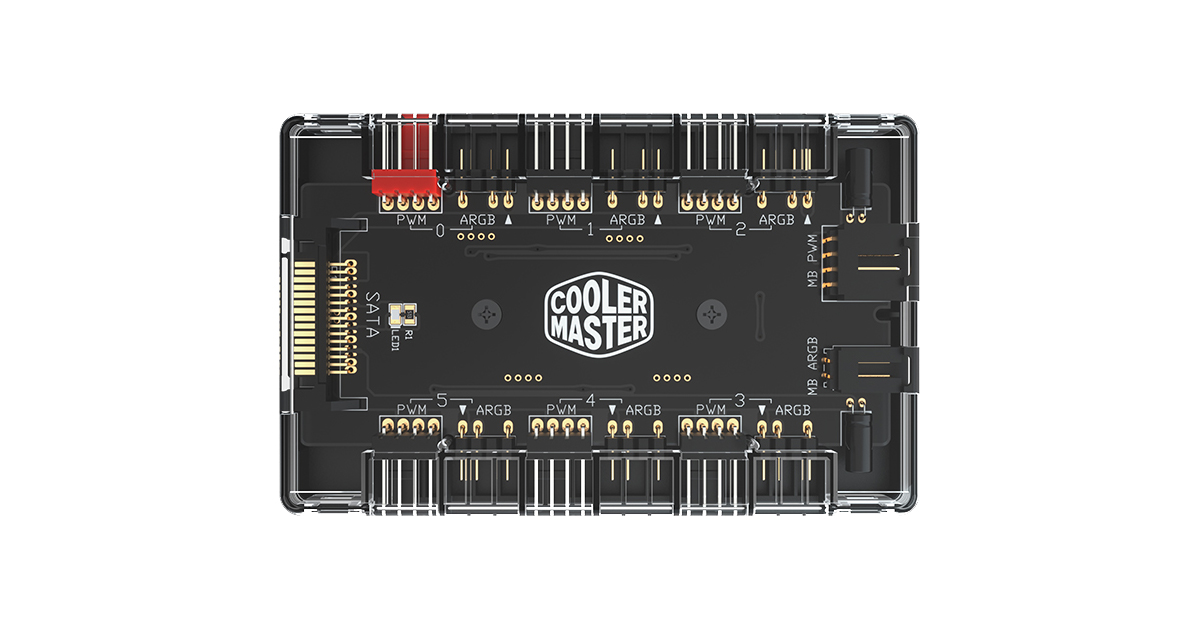
Here a photo of the controller :

View: https://imgur.com/a/fgjmuRb


So the solution, you would say, is to plug ARGB pins into the controller and fans control pins into « System fan » ports. Therein lies the problem : the fans given with the controller have proprietary ports and all the pins are black = I cannot say which ones are for ground, voltage, tachymeter, and signal. I just can see which ones are for ARGB, because these are clearly indicated on the board (5V, DI for Data and G).

The only clues that I have got are F+, F- and a blank square. And yes, you imagine that there is no data sheet, the controller was bought on aliexpress (this is a Bykski).

Finally, I wonder if the fans are PWM controlled or DC controlled ( in they are PWM, do they share with ARGB the same ground pin ? - because there are only 6 pins in total)

Thank you very much to those who will take the time to read me entirely, I don’t expect a lot because my issue is very specific but you never know...
 
Solution
You have little info on that proprietary system (means, non-standard, a design that the maker owns). But do tell us this about the hand-held control box it came with. Among its buttons, in addition to those for type and speed of the LIGHTING display, are there a couple to adjust the SPEED of the fans?

All we can go on here is SPECULATION based on the pin labels of the fan ports on that controller board. The "5V, DI and G" trio are for the ARGB LIGHTS in each fan: 5VDC power supply, Digital display control line, and Ground. The "F+ and F-" pins VERY likely are the two lines for the fan MOTOR, and I doubt that the unmarked pin does anything. In that case the fans are really of the older 3-pin variety with speed controlled solely by...

Lutfij

Titan
Moderator
Welcome to the forums, newcomer!

Are you working with this controller/hub;
?

If so, the controller will work a specific type of fan connector, meaning it's proprietary. Looking at the PCB labelling that hub does not have PWM management, instead the remote that the hub comes with will manage the fans, if not, then it's a fixed RPM.

I would advise on picking up a non proprietary hub akin to this;
or this;
http://cms2.deepcool.com:8080/site5...-12-Port-Addressable-RGB-Hub/2022/16061.shtml
and call it a day.
 

Ralston18

Titan
Moderator
Update your post to include full system hardware specs and OS information.

What/which "kit"? Bykski as I understand the post.

Bykski Link

Problem likely being the proprietary nature of the controller.

May or may not be viable. The first requirement being to determine the pin/plug mappings.

Wondering about supporting software as well.
 
Mar 28, 2024
9
1
15
Welcome to the forums, newcomer!

Are you working with this controller/hub;
?

If so, the controller will work a specific type of fan connector, meaning it's proprietary. Looking at the PCB labelling that hub does not have PWM management, instead the remote that the hub comes with will manage the fans, if not, then it's a fixed RPM.

I would advise on picking up a non proprietary hub akin to this;
or this;
http://cms2.deepcool.com:8080/site5...-12-Port-Addressable-RGB-Hub/2022/16061.shtml
and call it a day.
Thank you for answering me so quickly !

If I understand you correctly, it would be better to change the hub because it is proprietary, but what does it mean from the fans' point of vue ?
- The fans cannot work with any other hub because the port is proprietary ? (hardware)
- Or the fans cannot work with any other hub because they are calibrate on specific voltage etc... (software)

But it also means that in one case or the other I need to change the Bykski fans ? Thanks !
 
Mar 28, 2024
9
1
15
Update your post to include full system hardware specs and OS information.

What/which "kit"? Bykski as I understand the post.

Bykski Link

Problem likely being the proprietary nature of the controller.

May or may not be viable. The first requirement being to determine the pin/plug mappings.

Wondering about supporting software as well.
Thank for your reactivity !

I don't have full specs because this was given to me without any explanations.

What do you mean by proprietary ?

"The first requirement being to determine the pin/plug mappings" => this is the question of the thread !
I am desperate to know what pin corresponds to in order to "build" an adapter between the fans and potentially an other hub or in order to plug the fans (which have the female proprietary port) into my motherboard !
 

Paperdoc

Polypheme
Ambassador
You have little info on that proprietary system (means, non-standard, a design that the maker owns). But do tell us this about the hand-held control box it came with. Among its buttons, in addition to those for type and speed of the LIGHTING display, are there a couple to adjust the SPEED of the fans?

All we can go on here is SPECULATION based on the pin labels of the fan ports on that controller board. The "5V, DI and G" trio are for the ARGB LIGHTS in each fan: 5VDC power supply, Digital display control line, and Ground. The "F+ and F-" pins VERY likely are the two lines for the fan MOTOR, and I doubt that the unmarked pin does anything. In that case the fans are really of the older 3-pin variety with speed controlled solely by varying the Voltage on the F pins, NO ability to use a PWM speed control signal as 4-pin fans do, and NO fan speed signal sent back to a host header.

To re-wire every fan to new standard fan female connectors that fit standard mobo ports, the three Lighting control lines are clear, and all you need are the proper connectors to connect the right wires to. For the fan MOTORS you really have only two wires: the + and - wires for the motor, which go to Pins 2 and 1, respectively, of a standard 3-pin female fan connector. Then the mobo fan header needs to be set to use Voltage Control Mode (aka Dc Mode) to control its speed.

I would guess this controller does not use or pay any attention to fan speed. BUT is IS possible that the unmarked pin on the ports is the speed signal coming back from the fan motor and just ignored by the controller board. IF that is the case, then you might be able to connect that wire from each fan to Pin 3 of a standard female fan connector to feed that speed signal to a mobo fan header. FYI, a SPEED signal generated in a fan and sent to the standard mobo header on Pin 3 is a series of pulses, amplitude 5 VDC, 2 pulses per revolution of the motor. To detect that you'd need a small oscilloscope - a simple voltmeter will not tell you anything.

Another possibility is that the fan motors really are of the new 4-pin PWM designs almost, and that unmarked pin is for the PWM signal to get to each fan. That would mean that there really is NO speed signal from any fan back to that Controller board, which is possible - the speed info is NOT needed. However, that really would be an odd design.

You might consider splitting things up this way. For each fan's cable at the connector, at a short distance from that connector (so you can un-do all this and re-connect) MARK the F+ and F- wires. Cut them only, leaving the lighting wires intact. Splice onto the fan motor wires some extensions to standard 3-pin fan female connectors so they can reach your mobo fan headers, but realize that there still will be no speed signal from each motor reaching the mobo header. (UNLESS, of course, the unmarked pin's wire is fan speed and you splice that wire, too.) That way you could connect each fan's motor to a mobo header and control its speed by Voltage Control Mode. Although the header would not receive a fan speed signal (except as above), it does NOT require that to control speed. The header does use such a signal to monitor the fan for FAILURE, but that is not required. This leaves power and control of the LIGHTS still in the controller board you have.
 
Last edited:
  • Like
Reactions: Ralston18
Solution
Mar 28, 2024
9
1
15
Thank you for answering me so quickly !

If I understand you correctly, it would be better to change the hub because it is proprietary, but what does it mean from the fans' point of vue ?
- The fans cannot work with any other hub because the port is proprietary ? (hardware)
- Or the fans cannot work with any other hub because they are calibrate on specific voltage etc... (software)

But it also means that in one case or the other I need to change the Bykski fans ? Thanks !
By reading what I wrote I realized that my question is confuse :
I would like to know what pin corresponds to in order to use the fans from the same brand that ive got. If I want to use them with for example the cooler hub that you link, i need to know where to plug the pins of the fan because there isn't any adpter on the market between Bykski and non-proprietary hubs...
 
Mar 28, 2024
9
1
15
T
All we can go on here is SPECULATION based on the pin labels of the fan ports on that controller board. The "5V, DI and G" trio are for the ARGB LIGHTS in each fan: 5VDC power supply, Digital display control line, and Ground. The "F+ and F-" pins VERY likely are the two lines for the fan MOTOR, and I doubt that the unmarked pin does anything. In that case the fans are really of the older 3-pin variety with speed controlled solely by varying the Voltage on the F pins, NO ability to use a PWM speed control signal as 4-pin fans do, and NO fan speed signal sent back to a host header.

To re-wire every fan to new standard fan female connectors that fit standard mobo ports, the three Lighting control lines are clear, and all you need are the proper connectors to connect the right wires to. For the fan MOTORS you really have only two wires: the + and - wires for the motor, which go to Pins 2 and 1, respectively, of a standard 3-pin female fan connector. Then the mobo fan header needs to be set to use Voltage Control Mode (aka Dc Mode) to control its speed.

I would guess this controller does not use or pay any attention to fan speed. BUT is IS possible that the unmarked pin on the ports is the speed signal coming back from the fan motor and just ignored by the controller board. IF that is the case, then you might be able to connect that wire from each fan to Pin 3 of a standard female fan connector to feed that speed signal to a mobo fan header.

Another possibility is that the fan motors really are of the new 4-pin PWM designs almost, and that unmarked pin is for the PWM signal to get to each fan. That would mean that there really is NO speed signal from any fan back to that Controller board, which is possible - the speed info is NOT needed. However, that really would be an odd design.
Thank you so much it is exactly what I was looking for, you are amazing !
I forgot to take a picture of the female-port of the fans, and yet you deliver the perfect answer.
Can I post it when I get home, in order to have confirmation from you ?
Thank you again !
 

Paperdoc

Polypheme
Ambassador
You are welcome. You do need the details of how wires are connected on a standard 3-pin (or 4-pin) female fan connector - easy to find on-line, but I can help if needed.

Consider this. What you hope to do involves some detective work about what the unmarked pin is doing, if anything, and that requires some tools not in many home workshops. Then you have to find and buy some connectors and wire and do a bunch of cutting and soldering. An easier (but more expensive) route is to discard that entire fan system and just buy standard lighted fans. By the way, to do any of this the MOBO you have MUST have an ARGB header. IF it is an MSI mobo (you hinted that), they label such headers as JRAINBOW.
 
Mar 28, 2024
9
1
15
You are welcome. You do need the details of how wires are connected on a standard 3-pin (or 4-pin) female fan connector - easy to find on-line, but I can help if needed.

Consider this. What you hope to do involves some detective work about what the unmarked pin is doing, if anything, and that requires some tools not in many home workshops. Then you have to find and buy some connectors and wire and do a bunch of cutting and soldering. An easier (but more expensive) route is to discard that entire fan system and just buy standard lighted fans. By the way, to do any of this the MOBO you have MUST have an ARGB header. IF it is an MSI mobo (you hinted that), they label such headers as JRAINBOW.
Thank you so much again, really I am amazed !

I think I am going to try this maneuver... I will connect the unmarked pin to see if it is detected
But how would I be able to see if it is detected ? Will RPM be displayed? How can I be sure of not missing the data (I am sorry for this obvious question, it is my first pc !)

In other words, how will I be certain that the pin is or not detected ?
 

Paperdoc

Polypheme
Ambassador
First of all, look closely at the hole in the female connector on the end of the fan wires that mates with the unmarked pin of the board port. There may or may not actually be a wire there. IF there is, you should be aware that connecting a wire from the fan with unknown signal is a bit risky. But IF it has NO signal, there would be no problem. IF it has a standard speed signal, the mobo header you plug that into will show you a fan speed, typically in the range from 500 to 1500 RPM. If it has no speed signal, the header will show you no speed and may even pop up a screen warning that the fan has failed. If you get such a warning, my first suggestion would be to disconnect that wire since you do not know whether it is feeding some other signal into the header that could cause a problem. Then you can look in the configuration screens for that header for an option to ignore the speed signal and warning.
 
  • Like
Reactions: tylerdurdenthe1
Mar 28, 2024
9
1
15
First of all, look closely at the hole in the female connector on the end of the fan wires that mates with the unmarked pin of the board port. There may or may not actually be a wire there. IF there is, you should be aware that connecting a wire from the fan with unknown signal is a bit risky. But IF it has NO signal, there would be no problem. IF it has a standard speed signal, the mobo header you plug that into will show you a fan speed, typically in the range from 500 to 1500 RPM. If it has no speed signal, the header will show you no speed and may even pop up a screen warning that the fan has failed. If you get such a warning, my first suggestion would be to disconnect that wire since you do not know whether it is feeding some other signal into the header that could cause a problem. Then you can look in the configuration screens for that header for an option to ignore the speed signal and warning.
Ok thanks ! I shall do this and see what will happen !