Question Did I screw up?

May 23, 2022
10
0
10
Good day, everyone!

I'm fairly new to building my own PC and i'm trying my best to understand things. I do believe i've gotten everything down, but i've come across an issue that made me think I just goofed.

I recently bought a "MSI Mag Core Liquid 240R aRGB CPU cooler" alongside a brand new Ryzen 7 5800X, but whilst following instructions provided on a helpful YouTube video, and successfully mounting the hardware into the case i've come across the issue that the wires for the pump and the fans only have 3 pin holes. My motherboard, a "ROG STRIX B450-F Gaming II" appears to only have pins that have 4 pins. Maybe I'm missing something that perhaps you experts can point out, but did I just screw up in buying the right cooling fan?

Any help would be much appreciated. Thanks for your patience and guidance.
 
https://www.tomshardware.com/news/m...40r-360r-aio-coolers-due-to-sediment-build-up
You should check if yours qualifies for the recall, or simply return it for something else since you just got it. It'll just become a problem later.
I'm not sure if I can get a refund or return the thing, but this is mostly a temporary solution anyways. So if I wanted to use it for now and replace it in a few months, would that be okay?

Also, what do you mean by the connectors being keyed? Sorry, I'm not quite used to tech lingo just yet.
 
So if I wanted to use it for now and replace it in a few months, would that be okay?
That should be fine... experiences with those units have varied though.

Also, what do you mean by the connectors being keyed? Sorry, I'm not quite used to tech lingo just yet.
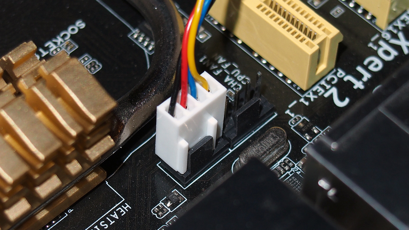
Take a look at the 3pin plugs. See how they have a pair of bars on one side?
iu
They slide in like that^.
 
That should be fine... experiences with those units have varied though.


Take a look at the 3pin plugs. See how they have a pair of bars on one side?
iu
They slide in like that^.
I'm sorry, but i'm incredibly confused. I was told to daisy-chain the two fans together and connect it to the pump header thing. I have done that (I think) but now i'm supposed to plug in this little 3 hole connector to a section called a "J-Rainbow"?

I haven't even gotten to that part you showed above, but I do have a cable that looks like that?

https://postimg.cc/gallery/f3MDzt2
 
When you posted this:
"I've come across the issue that the wires for the pump and the fans only have 3 pin holes."
And this:
"ROG STRIX B450-F Gaming II appears to only have pins that have 4 pins."
I said that the 4 pin headers on your motherboard are hybrids - they are backwards compatible with those 3pin fan and pump headers. You plug the 3pins into the 4pin headers such that the bars on the 3pins 'hug' the lip sitting over the header, like in the picture I included in the spoiler.


The daisy-chain is entirely optional, IF you have enough on board headers.
If you're going to use it, then you need to use the Y-splitter you have in postimage #3(the one on the left). Plug the 3pin connectors into the split ends and then plug it directly into one of the motherboard headers.


As for the LEDs, that one's a little over me, so I'll try to hail someone who does.
 
Cot a call from @Phaaze88 and now i'm here.

--

i've come across the issue that the wires for the pump and the fans only have 3 pin holes. My motherboard, a "ROG STRIX B450-F Gaming II" appears to only have pins that have 4 pins.

Sadly, the technologies are different between the two and you can't combine them.

On the regular +12V RGB header (4-pin), all LEDs of a primary color (R, G, B) are chained together and act simultaneously depending on the input signal. This makes individual LED addressing impossible.

Pinout:
pin #1 - +12V
pin #2 - G (green color)
pin #3 - R (red color)
pin #4 - B (blue color)

On the +5V RGB header (3-pin), there is LED driver control for each RGB LED package that translates the serial information coming in through the data pin into a specific output for that LED package it is attached to. That method makes single LED addressing possible.

Pinout:
pin #1 - +5V
pin #2 - data
pin #3 - empty (no pin)
pin #4 - ground

Plugging the 3-pin RGB connector to the 4-pin RGB header fries the LEDs since you'd be feeding more than twice the voltage to them (12V vs 5V). And even if the addressable LEDs somehow survive the initial power up, there's no data pin in the 4-pin RGB header to control the LEDs.

--

Now, your MoBo does have one 3-pin ARGB header. Take out holy bible of PCs (aka MoBo manual) and read page 1-15. In there, the 3-pin header is also shown where it is located on MoBo (bottom right corner, near bunch of other connectors).
 
Loads of confusion here, and I know the common labels on things make that happen often!

3-pin vs. 4-pin
These two labels are used for two DIFFERENT things all the time and cause trouble. To start, FANS come in two versions. The older design has THREE pins on its cable and their speed is controlled only by having the mobo fan header alter the VOLTAGE fed to the fan. So they are called Voltage Controlled Fans, but more commonly "3-pin fans". The newer type has FOUR pins on its cable and requires a different set of signals (including a PWM signal on Pin #4) from its mobo header for speed control. So we call them "4-pin fans". BOTH types of fan connectors have two ridges running down one side and these fit around a plastic tongue sticking up beside the pins of the mobo header. See the photo in the "spoiler" link in Phaaze88's post above. So either fan type CAN plug into either type of mobo fan header. On most of today's mobos ALL the fan headers are 4-pin. But in the configuration options found in BIOS Setup for these headers you can set which type of fan is plugged in so the header uses the correct style of control signals.

Fans with LIGHTS in their frames come with TWO cables from each fan. One is for the motor only, as above. The other is wider and is for the lights only, and connects to a different mobo header. Again there are now two dominant versions of how lights operate. The simpler one is called plain RGB and its connector uses FOUR pins. The more advanced design uses THREE pins, and it is called Addressable RGB or ADDR RGB or ARGB or Digital RGB. That is what OP's AIO system has in its fans and pump.

So in a lighted fan which is one unit, there really are two independent devices - a motor and some lights. The confusion happens because we use the labels "3-Pin" and "4-Pin" for both classes of device, even though there is NO relationship between the two!

Connecting Several Devices to One Header
If you have many fan headers you can connect each fan to one header, no confusion. But if you're short of headers you can use a SPLITTER to connect two or more to one header, subject to a limit on maximum current draw for all the fans on one header. The limit is 1.0 A max, and most fan MOTORS draw at max 0.10 to 0.25 A, so connecting three (sometimes more) fans to one header his way is OK. For MANY fans you may need a different device called a fan HUB, but the labels used by sellers on these two devices are badly misused and cause confusion. Briefly, if the device has a special "arm" that must connect to a power output connector from the PSU, then it is a HUB and NOT required for small numbers of fans. OP, in your case the AIO system comes with a small Splitter with two output arms that you use to connect BOTH rad fans to ONE mobo header. Of course, this unit has connectors on it that match the MOTOR cable connectors on the fans. Just to head off one more confusion spot, the two outputs of this Splitter look a little different - they have 4 pins, but one will be missing Pin #3. That is because of a limit on what the mobo header can do with speed signals, but don't worry about that. Note that this is NOT a daisy chain system - you are using the SPLITTER supplied with your AIO system for the fan MOTOR cables.

In a similar manner one might need a way to connect the LIGHT cables from several fans to a single LIGHT header on the mobo. Indeed, OP, your mobo has ONE header for ARGB lights called the "ADD_HEADER" at the mobo bottom edge near the front - see item 10 in the mobo manual diagram on page 1-2, and also p. 1-15. Do NOT try to use the adjacent item 11, which is a header for the other system, plain RGB. For this, one way is to get a similar Splitter for lights. But your AIO system comes instead with a cable system on each fan and on the pump that includes BOTH a male and a female ARGB 3-pin connector and this allows you to connect all three in a "daisy chain" manner to that one mobo ARGB header. You do not need a ARGB Splitter. You plug the female lighting cable connector from one fan into the mobo header, then the female from the second fan's lights into the male from the first, and likewise add the pump lights to this chain. Note that the daisy chain system of connections applies ONLY to the LIGHTING cables.

Where to Connect Fans and Pump
Your mobo has sufficient fan headers to do this neatly. Background: any fan header has an important secondary function: monitoring the speed signal coming back to it from the fan. It does not use this for speed control, but it DOES use it to detect fan FAILURE (no fan speed signal). If failure happens it pops a warning on your screen. But specifically for the CPU_FAN (and CPU_OPT in your case) it does more if failure occurs. It may well shut down your system completely and refuse to let you start up if there is NO fan speed signal at those headers. That is to prevent damaging overheating to a CPU chip with no cooling. So something must be plugged into at least one of those two headers. (Those two operate as twins of each other.) In ADDITION on your mobo, OP, there is a header called AIO_PUMP - see manual p. 1-9, item D - particularly for your pump which also does this careful monitoring for failure. Which to where? In an AIO system the critical unit that MUST not fail is the PUMP - no pump, no heat movement from CPU to rad. A fan failure at the rad will reduce cooling, but that will result is a slow rise in CPU temperature that will be handled by another system anyway. The PUMP unit must be plugged into the AIO_PUMP header on your mobo. In your case, OP, that cable actually comes from the RAD (it feeds power to the pump that way) and has THREE holes in it like a 3-pin fan would have. The two rad FANS (using the SPLITTER) should be plugged into the CPU_FAN header. In an AIO system the pump is supposed to run full speed all the time, and that is what the AIO_PUMP header will do for you. Control of the CPU temperature is done only by changing the speed of the rad FANS plugged into the CPU_FAN header.
 
Last edited:
To start, FANS come in two versions. The older design has THREE pins

I feel that i need to make a correction here:

Fans that connect to MoBo internal fan header, come in three versions:
  1. Oldest - 2-pin
  2. Newer - 3-pin
  3. Newest - 4-pin

Now, 2-pin fans are relatively rare within consumer segment since for consumers, 3-pin is standard. 4-pin is also making it's stand. However, that doesn't mean 2-pin fans are gone. No, they are not. In industrial segment, most of the fans are 2-pin. E.g Delta Industrial fans. Oh, older consumer PCs, e.g 10-20 years old, can easily come with 2-pin fans that connect to MoBo.

With 2-pin fans, it's simple, plug it in and it will run 100% at all times. That is, unless you don't have voltage control before fan connector. Since 2-pin fan doesn't feedback it's RPM back to the MoBo, software wise, it's hard to tell what it's max or current RPM is. Only visual control of the fan itself would enable semi-effective speed control of it. But 2-pin fans are designed to run 100% at all times.

--

The three above are most common, aka "default" fan connectors, but fans aren't limited with only those three connectors. There is also a variant of 2-pin fan, which has big MOLEX connector at the end and instead of plugging into MoBo fan header, it will plug into PSU's MOLEX connector. <- That fan will run 100% at all times as well.

And then there are plethora of proprietary connectors as well, that work with only same brand hardware. E.g good example would be Aerocool Mirage 12 ARGB Pro, which has proprietary 6-pin connector and works only in Aerocool RGB control hub.

--

I've seen many consumers buying (A)RGB fans and hoping to connect them to MoBo, for unified software control, but end up with proprietary fan connectors, that can't be connected to MoBo at all. Only sometimes, when compatible hardware exists from same brand. <- Many cheap (A)RGB fans come with those proprietary connectors.

But if you're short of headers you can use a SPLITTER to connect two or more to one header, subject to a limit on maximum current draw for all the fans on one header. The limit is 1.0 A max, and most fan MOTORS draw at max 0.10 to 0.25 A, so connecting three (sometimes more) fans to one header his way is OK.

Here, good practice would be to keep in mind, that for single MoBo fan header, 2 fans can be connected by Y-splitter.

And if there is need to connect more than 2 fans, better check the fan Amperage, so that all combined, doesn't surpass the 1.0 A rating of MoBo fan header. E.g if single fan would be 0.299A, i wouldn't connect three of them to single header, despite being "very" close. Instead plug the 3rd fan to somewhere else, or buy a fan hub that is powered by PSU.
 
  • Like
Reactions: Paperdoc