[SOLVED] Ethernet connecting a PC with router in separate room ?

GoldenCrepe

Reputable
Jan 1, 2020
34
0
4,540
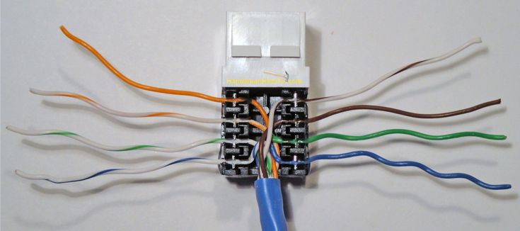
My computer is in a separate room from my router. I'm getting spotty internet connection wirelessly, and am hoping to be able to connect my computer through the wall to my router. Please be patient, as I don't know much about this topic, but I'm willing to learn.

My modem is plugged into the wall, with the router plugged into the modem. Here's the port behind my modem.
Here's the port behind my computer.
There's a whole puzzle of cables in my attic which I assume lead to different parts of the house.

Currently, my modem is plugged in by coax cable (I think). How would I connect my router into the wall to work with my PC?
 
Solution
If you swap green and orange only on 1 end it will be what the call a cross over cable. Not really used any more and if the ports are smart enough it won't hurt. Many times it just runs at 100mbps rather that 1gbit.

The only risk with having multiple wires hooked up to the patch panel would be if for example one of the cable had a short on them or if it was say connected to a actual telephone. It would be best if you could only have the 2 cables you are actually using but in theory a extra wire connected to nothing would not hurt.

The $20 or so for a cable tracker makes this project much easier. It tends to be very easy to be sure you have the correct cable.
I would first try to document and label where the cable in the attic are going.

I see both coax and what appears to be ethernet in the computers room. The one behind the modem looks like it might have also had ethernet but they are covered ?

So if those are actual ethernet cables can you find out where they go. If they are all just disconnected in the attic you might be able to connect a ethernet cable between the 2 rooms with a simple coupler. If you can get to the wall where the modem is you could also drop a new ethernet cable down the wall if they do not exist and then connect that to the cable going to the computer room.

If the ethernet cables go to some central panel then you could connect them their or you could use a small switch if you wanted to turn other rooms on ethernet in the future.

I would try the ethernet option first because it is going to be cheaper.

If you can't figure out the ethernet you can likely use MoCA on the coax instead. The 2.5 versions can get full gigabit speeds but will cost you just over $100 for a pair. The modem and the moca devices should be able to share the same coax if you need to.
Key to making MoCA work is that the coax cables in both location must somehow be connected. Many times these are just spliced together in the attic with a splitter. Check the splitter and be sure it is rated to at least 1675, many are over 2000 but older ones that are under 1000 will not work.
 

GoldenCrepe

Reputable
Jan 1, 2020
34
0
4,540
Thank you for your response! I'm going to attempt to make this as streamlined as possible, but there's a lot of points to make on my end.

A few years ago my parents were having issues with our Cable TV. Long story short, most of the coax cables in the attic aren't plugged into anything (besides "Main Trunk In" which is plugged into "living room" where the modem is).
Some rooms are labeled, and some rooms aren't. It just so happens that the room I need it in is not labeled.

The wall cover in the modem image has ports for Ethernet, but I unscrewed it to look behind, and there is no Ethernet cable already in place. That being said, I do have access to that wall, though it might be a bit difficult to weasel a cable down.
The wall cover in the computer image has a coax cable and two CAT 5e cables, but I can't seem to find out where they lead to in my attic.

Here's three more images of the port behind my computer. A picture says a thousand words, so I have three-thousand for you right here!

I also have this (extremely messy) panel in a closet upstairs that might be of some use.

Here come my questions:
  1. How do I find out which ports go where? I can't find any Ethernet out ports in my attic, so I assume it has something to do with that closet panel. I observed that the coax cable behind my computer is white, and there's only ~4 white coax cables in my attic. Do I use trial and error? What would I plug them into to test them?
  2. How would I add an Ethernet cable to the area behind my modem? Is it as easy as dropping a cable down and pulling it out of the wall cover, or do I need to do some wiring?

Again, thank you for your help.
 
With that many wires I would hope there was at least one near the modem.

Unfortunately all that is wired for telephone so you are going to have rip it out and start again. The good news is the wire itself says it is cat5e on it so it will work fine for data up to 1gbit.

The wall jacks also appear to be cat5e data jacks so it is just a matter of putting all the wires in the proper place. It should be just a matter of matching the color pattern on the jacks.

In the main closet room you have 2 options. You can buy a patch panel for data, look very similar to the telephone one you have. Or you can just put rj45 plugs on the ends of the cables. You would then either connect the wires together for the rooms you want if you only want 1 or you buy a small switch and then you can have live ethernet ports in every room.

Finding the wires can be tricky. You can use the old battery and led or test meter find them. You can buy special tools to find wires that are not real expensive....well most are cheap not sure what the expensive ones do. This is just one example you can find cheaper ones than this but this also will test the wires are properly connected when you do the next step of reconnecting the wires to the jacks


What this does is put a small radio signal on the wire and when you get the receiver near the proper wire you can hear the tone. This one does not have a coax adapter but you can just hook one of the test clips to the center wires and it will work fine.
 

GoldenCrepe

Reputable
Jan 1, 2020
34
0
4,540
With that many wires I would hope there was at least one near the modem.

Unfortunately all that is wired for telephone so you are going to have rip it out and start again. The good news is the wire itself says it is cat5e on it so it will work fine for data up to 1gbit.

The wall jacks also appear to be cat5e data jacks so it is just a matter of putting all the wires in the proper place. It should be just a matter of matching the color pattern on the jacks.

In the main closet room you have 2 options. You can buy a patch panel for data, look very similar to the telephone one you have. Or you can just put rj45 plugs on the ends of the cables. You would then either connect the wires together for the rooms you want if you only want 1 or you buy a small switch and then you can have live ethernet ports in every room.

Finding the wires can be tricky. You can use the old battery and led or test meter find them. You can buy special tools to find wires that are not real expensive....well most are cheap not sure what the expensive ones do. This is just one example you can find cheaper ones than this but this also will test the wires are properly connected when you do the next step of reconnecting the wires to the jacks


What this does is put a small radio signal on the wire and when you get the receiver near the proper wire you can hear the tone. This one does not have a coax adapter but you can just hook one of the test clips to the center wires and it will work fine.

Right now, I only need Ethernet in one room. Everything else is wonderfully covered wirelessly.
Let's say, hypothetically, that I only care about the Ethernet ports. Step one would be to figure out which Ethernet cable goes into that closet. Would the tester you linked work to find it? Step two is to unlink it with the phone board, and wire it to a RJ45 plug. Step three is to get a very long Ethernet cable, connect both of those cables together, drop that behind the wall of the modem, and then connect the router to that.

Do I need a specific Ethernet cable to go in the wall panel behind my modem, or would a normal one work?
 
Last edited:
What I would do with the tester is let everything plugged into the telephone patch thing. You can them plug the sender in each room using the telephone cable in the jack. Then go to the panel and move over the wires until you get the strongest signal. Since they are all hooked together there will be some bleed but it tends to be very obvious. You can then label as many cables as you feel you might need. I would find all that go to the room you want just in case there is some issue with one. I suspect you have 2 per room.

Generally you would use bulk cable and then put either rj45 ends on them or connect them to wall jacks. If you use premade cables you will have to drill much larger holes though the top of the walls in the attic. It is almost trivial to get wires run when you can get a drill into the top of a wall....it is a big harder if there is insulation in the wall. When there is insulation you will need something long and flexible but still stiff enough you can push it though insulation. You will find all kinds of different fiberglass "fish" rods.

In any case make sure you get solid core pure copper cable with wire size 22-24. There is massive amounts of fake stuff so read all the fine print. Most bulk cable is solid core but many times patch cable is made of stranded wire because it is more flexible. Problem is if you cut the ends off it takes a different and much more uncommon end that the ones that go on solid core cable. Stranded cable will also not correctly fit into the the punch downs in wall jacks.

Hard to say what I would recommend as the easiest. I would first check if there are any other option to use your existing in wall cables. There is so much cable there almost has to be one run into that room. Take a flashlight and look in the wall maybe it was just disconnected and is hanging loose. Another consideration would be what is on the other side of the wall. Is there another room where you could run a cable though the wall and hook to a jack in the other room...of course it would have to be close by or you would have a messy looking install.
 

GoldenCrepe

Reputable
Jan 1, 2020
34
0
4,540
What I would do with the tester is let everything plugged into the telephone patch thing. You can them plug the sender in each room using the telephone cable in the jack. Then go to the panel and move over the wires until you get the strongest signal. Since they are all hooked together there will be some bleed but it tends to be very obvious. You can then label as many cables as you feel you might need. I would find all that go to the room you want just in case there is some issue with one. I suspect you have 2 per room.

Generally you would use bulk cable and then put either rj45 ends on them or connect them to wall jacks. If you use premade cables you will have to drill much larger holes though the top of the walls in the attic. It is almost trivial to get wires run when you can get a drill into the top of a wall....it is a big harder if there is insulation in the wall. When there is insulation you will need something long and flexible but still stiff enough you can push it though insulation. You will find all kinds of different fiberglass "fish" rods.

In any case make sure you get solid core pure copper cable with wire size 22-24. There is massive amounts of fake stuff so read all the fine print. Most bulk cable is solid core but many times patch cable is made of stranded wire because it is more flexible. Problem is if you cut the ends off it takes a different and much more uncommon end that the ones that go on solid core cable. Stranded cable will also not correctly fit into the the punch downs in wall jacks.

Hard to say what I would recommend as the easiest. I would first check if there are any other option to use your existing in wall cables. There is so much cable there almost has to be one run into that room. Take a flashlight and look in the wall maybe it was just disconnected and is hanging loose. Another consideration would be what is on the other side of the wall. Is there another room where you could run a cable though the wall and hook to a jack in the other room...of course it would have to be close by or you would have a messy looking install.

I looked behind the port near the modem, and found a CAT 5e cable just hanging there! Please correct me if I'm wrong, but now all I should have to do is wire it up to a CAT 5e coupler, and install that into the wall.

Here's a poorly-drawn diagram of what I have so far. Once I find the cable that goes behind the PC, how would I connect the two together? Make one male rj45 and the other female rj45 and plug them together? Wire them together completely? What options do I have?
 
So if we assume you fix/rewire the wall jacks so they use correct wire patterns there are a couple solutions in the panel you have marked ?

So if this was my house I would be putting in a full patch panel and a switch to connect everything too but that is a lot of effort if you feel you will only ever use just 1 wire.

Note when you redo the wall jacks untwist as little wire as possible. In a professional installed the outer cable most cable insulation will be almost inside the jack and with only enough of the actual wires untwisted to connect to the metal pins.
This is some random image I found
https://tonetastic.info/read/rj45-w...to-install-an-ethernet-jack-a-home-network-22

Note the color pattern can be a bit different from keystone to keystone be sure to match the proper colors for yours.

So there are a couple ways to directly hook 2 wires together.

First the quick and dirty way which I don't really recommend but would likely work is to just strip off the insulation and twist the wires of the same color together and use electrical tape to prevent shorting. Ethernet cable uses the twists between the pairs to isolate signals and doing this messes that up a bit. On shorter connections (ethernet can go to a full 100 meters) it likely will work.

The more common way is to crimp ends on the cables and then use a simple rj45 coupler to connect them. You will need to buy a crimp tools and more important learn to use it. Crimping ends on cables is a practiced skill and you will likely make many bad ones to start.

Another solution is to use a rj45 splice. These are not real common but the concept is, large data centers have used huge punch down patch panels to connect wires.
https://www.amazon.com/Junction-Pack-Unshielded-Punch-Listed/dp/B095JYHXKJ

Technically you need a 110 punch down tool to install the wires. You kinda need tool to install the wall keystone wires also. You can if you are very careful used a small screw driver and a wire cutter, being very careful to only push on the wires and not on the center of the connector.
 
So another thought after looking at that messy photo of the patch room.

What you could do is remove all the cables from one of those patch boards. Then the 2 cables you want to keep cut the wires much shorter (again untwist as little as possible) and then use any 2 of those connections making sure the colors match properly. All those connectors are connected together. if you were to just use 2 of them then it would be ok to splice a ethernet cable. Nobody would spend money to do it that way but since you already have the telephone patch panel you might as well use it. Again make sure every wire except the 2 you are splicing are removed.
 

GoldenCrepe

Reputable
Jan 1, 2020
34
0
4,540
I'll probably use the splice or the patch room method. If I use the patch room method, would I just need to connect both of those wires on one board, while removing everything else?
Do I remove all the wires on the other board as well?
Do I need to have them in specific spots?
I know it's meant for telephones, so do I need to wire it in any specific way to make it work for internet?
Here's a close-up image, if that helps any.
 
You can use any you like. The are extremely simplistic. The orange on each it connected to the orange on all the other ones. The green blue brown and all the stripped color ones are similar the corresponding color on each connector are hooked to the same color on the others.

It really doesn't make any difference if you remove the other plate the remote ends of the wires are just hooked to dead wall plates so you can leave them connected or you can remove them. In the long run you might consider something like this to replace the phone boards

https://www.amazon.com/Open-House-H628-Termination-Hub/dp/B00013BNVG

This one is expensive but it is a exact size replacement for the phone ones. There are other cheaper brands that will fit if you wanted to dig around. These unlike the phone ones only connect between the rj45 jack and the patch connection directly below it.
 

GoldenCrepe

Reputable
Jan 1, 2020
34
0
4,540
So, really, since they're all connected anyway, all I would have to do is connect the router, right? I wouldn't like to disconnect all those wires if I don't have to, since I've never done this before. Since the others are just leading to unused ports, would it matter if I just left it as it is?
If yes, the final step would be to connect the cable behind the modem to a rj45 couplet, then plug it into the router. The data will go to that panel, and redirect to the only place it's being used: my computer. Does this sound correct?

Also, did you mean it doesn't make any difference if I remove the cables from the other board, or it doesn't make any difference if I remove the cables from any board?
 
I meant the other board. I would still remove all the cable from the board you are using as a dumb splice. Unless you checked every remote jack you won't know for sure if there was something strange with the wires. On the panel on the far left connector you will see they ran a orange wire from the brown connector to the orange connector and the same with the blue and green. This will cause massive issues if you connect the pins together like this on ethernet cables.

I guess it depends on if you ever feel you might need telephone in the future. Almost nobody uses a hard wired phone any more. In addition if you needed phone in the future you can plug phone into data jacks directly and just hook them to the incoming phone line rather than a router or switch.
 

GoldenCrepe

Reputable
Jan 1, 2020
34
0
4,540
Hopefully my final question: How would I wire the cable to the board after taking everything else out? I can find stuff online for wiring an Ethernet cable to a rj45 tip, but not for connecting it to this panel.
Right now, there are two separate cables being connected to one "row". Would I need to connect both cables I'm using to the same row? It seems that there are 8 wires in each cable, and 8 places to connect them in each row.

Some colors have stripes on them, but there are no striped stickers on the panel like there are in rj45 connectors.

Assuming I use two different "rows" for each cable, does it matter which rows I use?
 
So if you mean physically you need a 110 punch down tool but you can use a screwdriver if you are careful. They make cheap plastic ones but in this case I suspect it is all shipping costs.
https://www.walmart.com/ip/Leviton-40865-Plastic-110-Non-Impact-Punch-Down-Tool/259031653

If you mean how do you match the colors. So if we ignore things like they have orange wires connected to brown and blue wires hooked to green.

If you look at say the first vertical row it has a orange wire in the first position. On the second row it also has a orange wire in the first position. These 2 wires are connected together.

In the second position it has orange/white in both. These also are now connected together BUT they are not connected vertically. The orange and the orange/white are not connect to each other they are 2 different connections.

It is customary to hook these up solid wire then striped wire. In this case you would go from top to bottom

Brown-brown/white-green-green/white-orange-orange/white-blue-blue/white.

This makes it some what simpler to understand but the plastic and the wires do not actually know what color they are. It technically doesn't matter as long as you are consistent. What ever you put in the top position of jack 1 will connect to the top position of jack2 no matter what color the wires are. Also all the other vertical rows/jacks are also connected so if you put a third wire in position 1 on the third jack on all 3 wires in position 1 would be connected to each other. This never works for ethernet but does for telephone.
 
Yes you really want all 4 pairs of wires so you get gigabit speeds.

For a phone they are likely using the blue pair on 4,5 and the orange pair on 3,6.

Data for 100mbps uses the pairs on 1,2 and 3,6 but if you just added the extra wires on 1,2 but left the 4,5 pair it might get confused because it has part of a gigabit connection and a 100mbps. It should in theory figure it out and drop to 100mbps.
Still if you are going to mess with this you might as well do it correctly.

First look up and understand 568a and 568b color pattern.

So if after you check the blue wires are actually on 4,5 and the orange are on 3,6 you might just be able to add the other wires. You would want to use 568a in this case....so you don't have to move the orange wire.
You should be able to put the green pair in 1,2 and the brown pair in 7,8
 

GoldenCrepe

Reputable
Jan 1, 2020
34
0
4,540
I come back two days later, slightly discouraged. I got my punch-down tool, wired up all of the cables, and had no success.

Here's the newly-wired panel. I found two cables that could possibly be from the port behind my router, so I just wired them both together, just in case. I only found one cable that I believe is from the port behind my computer, although I'm not 100% sure on that. Anyway, I wired it in, plugged my computer and router into the wall, and saw no results.

I didn't quite understand your last message, even after looking at 568a patterns, so I wired the closet panel to what you said before:
Brown-brown/white-green-green/white-orange-orange/white-blue-blue/white.

If you were talking about rewiring the wall, I hope I followed your instructions here.

Is there anything wrong with my wiring? Maybe I just didn't find the right office cable?
 
Last edited:
At first I was like that won't work when I looked at you central panel but it should be fine as long as you do not try to use both ports going to the living room at the same time.

The wall jacks are good as long as you did them all like that.

This is where you need a test device to be sure. The wire might look perfectly fine but maybe the cutters in the jack did not get all the way though the insulation. All it takes is 1 wire to have issues and it will not work. Not sure what to recommend you have done all the connections to the jacks and the panels correctly. This leaves you are using the wrong cables or there is some defect you can not see. This can be a very tedious thing. I must have spent 2 hours trying to fix a jack and it was because the wires were old and the brown and orange were almost the same color and I messed it up. Your though look very good and should be working.

Note here is a example of jack. This is one of those thing you see when you have been trained to make them correct and you see a DIY install. What I am pointing out here is how little wire is untwisted and how little of the outer insulation is cut back. It generally makes no difference at all but it bugs me :)


The pattern on this keystone is very different than your, ignore that you did it correctly by matching the color on yours.
 

GoldenCrepe

Reputable
Jan 1, 2020
34
0
4,540
I know I got the one behind my computer right. If I happened to incorrectly do the one behind the router (swapped green and orange), would that be able to mess it up?

Also, to clarify, there are two Ethernet wires in the wall behind the router. Only one is wired into the RJ45 coupler, but I don't know which one that is once I get to the attic. So, one is actually connected to something, and the other is connected to nothing. Since I don't know which one is actually connected to the coupler, I wired them both into the closet panel.
 
Last edited:
If you swap green and orange only on 1 end it will be what the call a cross over cable. Not really used any more and if the ports are smart enough it won't hurt. Many times it just runs at 100mbps rather that 1gbit.

The only risk with having multiple wires hooked up to the patch panel would be if for example one of the cable had a short on them or if it was say connected to a actual telephone. It would be best if you could only have the 2 cables you are actually using but in theory a extra wire connected to nothing would not hurt.

The $20 or so for a cable tracker makes this project much easier. It tends to be very easy to be sure you have the correct cable.
 
Solution

GoldenCrepe

Reputable
Jan 1, 2020
34
0
4,540
If you swap green and orange only on 1 end it will be what the call a cross over cable. Not really used any more and if the ports are smart enough it won't hurt. Many times it just runs at 100mbps rather that 1gbit.

The only risk with having multiple wires hooked up to the patch panel would be if for example one of the cable had a short on them or if it was say connected to a actual telephone. It would be best if you could only have the 2 cables you are actually using but in theory a extra wire connected to nothing would not hurt.

The $20 or so for a cable tracker makes this project much easier. It tends to be very easy to be sure you have the correct cable.
I went out and bought a cable tracker, tested the attic-to-office cable with success, and then tested both attic-to-living-room cables, with neither working. I traced the cables back to a bundle, and I found out that I managed to trace both cables incorrectly, leading to it not working at all.

I fixed the issue, wired all the cables back up, tested it on my PC, and success! To think that all of that stress happened because I confused two cables with two completely separate cables.

Thank you so much for your help. Instead of spending $300, I spent $30, and I learned some things along the way!
 
This tends to be why people put in patch panels to keep everything very neat and well marked. It is so nice that these tone tools have gotten so inexpensive. I remember stripping off wires and using batteries and led to do this.

At least when you next need to find a cable next time you have the tool.