- Mar 23, 2020
- 1,739
- 239
- 13,090


In general - it is uncommon to have a bad flash, but it is indeed possible. In many cases, it is the improper electronic components handling (static electricity discharge) that makes you look for this guide. This guide is also helpful for AMD users that do not have their new CPU supported with their old BIOS and cannot borrow one that is supported.
- Unless you are sure that following is your only option, try to use a more convenient method - take it to a tech and get him to do it for you or send the board for RMA repair are two most suitable IMHO. Note: Some motherboards have a way to recover with a USB stick or DUAL BIOS, but that only works if the feature survived the bad flash - those features are usually a part of the BIOS software itself and at least one chip has to be good for dual BIOS to work.
- Read the guide in its entirety first, if it is not something that suits you, or you do not fully understand it- go for another option.
- You are committed - you do understand that you may accidentally do damage beyond board recovery and ready for the outcome.
- Getting the tools:
- CH341a (or any other SPI flash programmer of your choice and availability with suitable software)
- SOIC-8 or SOIC-16 (depends on the chip, skip this if you are comfortable with SMD soldering and use the supplied soldering pad, but in this case, you probably do not need this guide)
- 1.8v Adapter (IMPORTANT!! Your BIOS chip may require a different voltage, google your chip datasheet before buying)
- Or the whole bundle in one click
- Strongly recommended but not required - Digital Multimeter (the cheap ones are OK too). Just skip the steps that require it if you do not have one.
- Strongly recommended but not required - Static Mat (you can get by without but it may bite you in the back)
- Programming software and drivers. (If another flashing tool is used - use a suitable software and driver for that one.)
- Getting the BIOS file to flash - techpowerup.com has a great VGA BIOS collection, for motherboard BIOS - use the manufacturers' website to find one.
- If you happen to have Asus or Asrock motherboard that comes with ".cap" BIOS file - you need a tool to convert it to a flashable image (.rom or .bin are ok)
- Prepare your workspace:
- Put an antistatic strap on your hand.
- Prepare a static-safe surface, I strongly recommend using a static mat.
- Get a good lamp and a magnifying glass (optional)
- Take everything off the board (all components and all connectors, even the 3v cell if it is detachable) and place the board on the mat.
- Identify your BIOS chip and check if it is flashable on the board:
- There is a variety of ICs used, the common ones that I see are Winbond and MXIC ICs, usually have 8 or 16 legs, they look like those:

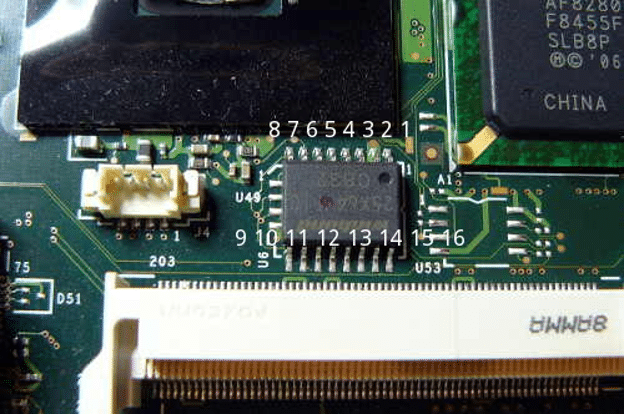
- It is tiny, usually located by the 3v battery connector but can be anywhere on the board (including the back). If you find the IC you think is the BIOS, google its' datasheet (I will use the 25Q128FVSQ datasheet as an example, the last two letters signify the package type for Winbond). Make sure it is an SPI Flash memory chip. You will need to find out:
- the operating voltage.
- For 1.8v the adapter should be used.
- If the chip is 3.3v you can mod the ch341a to support 3.3v.
- Natively ch341a is 5v.
- verify the pin layout even though it is standard, you will be able to re-confirm it is an SPI flash
- the operating voltage.
- set the digital multimeter (DMM) to measure resistance (usually the Ω sign)
- touch the probes together and note the reading (should not be >1 Ω, ideally 0)
- touch (firmly) black probe -> leg #4 of the chip, red probe leg#8 and note the reading-
- Anything below 1kΩ -> STOP! The chip has to be removed off the board for flashing.
- Anything above 1kΩ -> Proceed at your own risk. The result is not guaranteed but no obvious damage is expected at this point.
- There is a variety of ICs used, the common ones that I see are Winbond and MXIC ICs, usually have 8 or 16 legs, they look like those:
- Prepare the flasher and the software:
- Assemble the SPI programmer (for 1.8v I need a level shifter which came with the package) fully assembled (with a clip in your case) it will look like this. It should not be connected to anything yet.
- Download the software package for the flasher and extract it to a directory of your choice ("C:\Portable\AsProgrammer1.4\" for example)
- Look for a BIOS file you need to program and extract it to a temporary directory ("C:\Portable\temp" for example)
- Verify that everything is connected properly and connect it to USB 2.0 port of a PC:
- Attach the programmer to any USB 2.0 port (I would avoid the front panel ones, those are usually worn out)
- Run (as administrator) C:\Portable\AsProgrammer_1.4.1\CH341-Drivers\CH341Parallel_driver_support WIN7\CH341PAR.EXE and install the drivers for the connected device so that the software can claim it
- Launch C:\Portable\ch341a\AsProgrammer_1.4.1\AsProgrammer.exe (as Administrator so that it has access to my files for writing) and select ch341a from the Hardware in the top menu
- Close the software and disconnect the flasher from USB port
- Flash the BIOS/vBIOS:
- Attach the clip firmly to the BIOS chip with the red wire on the ribbon cable towards pin#1 (the dot on the chip is the key to reading the pin layout you got at step 6.2.2 above)
- Attach the flasher to the same USB port and run the software
- Press the Read ID button (IC-sign ?) and select my IC from the populated list
- if you get this reading or your chip is not recognized at all - the clip is not attached properly or the memory chip is dead or the assembly is not right or something is defective - DO NOT PROCEED!
- if the populated list has a different model than yours, your chip is not in the database, you can still try at your own risk - the standard is still there
- Save the current content of the IC (just in case you need it to revert your tampering) by pressing Read IC (IC-sign and ->) save it to a file backup.rom
- Open the file to be written (click the folder icon and pick the extracted file from step 7.3)
- Launch the programming sequence (Press on the black pointer on the icon with a red arrow pointing towards the chip and select the sequence)
- Once done, verify it again to make sure it stays there after a minute (the Icon that has the"=")
- Close the software, disconnect the flasher and the clip.
- Assemble your hardware and try. If it helped - give this page a "like" so we know if it is actually useful 🙃
Last edited:


") (Sorry for my english😬)
(Sorry for my english😬) Twitter