Question Sanity check/final check on my cooling please ?

Feb 14, 2024
6
0
10
Hello!

I have a plan to set my ARGB fans here and I’d like some opinion/confirmation that it makes sense.

First, here’s what I’m using
  • Case: NZXT H6 Flow
  • Mobo: MSI MAG B760M Mortar Wifi II.
    • The JARGB_V2 connectors allow you to connect the ARGB Gen2 and the ARGB-basedLED strips. The JARGB_V2 connector supports up to 240 individually addressable RGB
      LEDs with maximum power rating of 3A (5V)
  • 3 x 120 mm fans for front-right: Thermaltake CT120 ARGB Fan White
  • 3 x 120 mm fans for top: the same Thermaltake CT120 ARGB Fan White
  • 1 x 120 mm fan (non-RGB/non-ARGB) for the rear: this is the one that is provided by NZXT (F120Q)
  • 2 x 140 mm fans for the bottom: Thermaltake CT140 ARGB Fan White
  • CPU: Thermalright Peerless Assassin 120 SE White ARGB
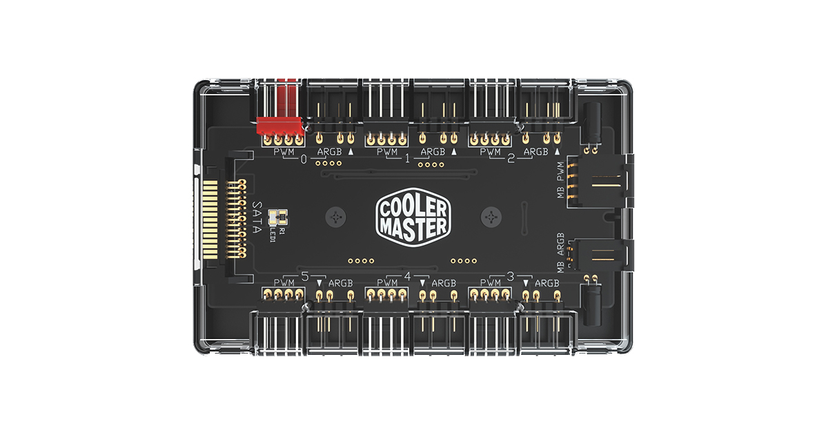
  • Fan controller: DeepCool SC790 Fan Hub 2in1 PWM & ARGB 6-Port 5v-3pin

My main concerns are overloading/maxing out the current and not knowing how to connect the CPU cooler PWM and LED. Right now, I have no idea which fans will act as exhaust and which fans will be intake but does that really matter if all that changes is the orientation of the fans?

My plan
  • Will skip talking about the CPU cooler til the end.
  • Daisy-chain the 3 x 120mm front-right CT120 ARGB fans. The total amp for this (I believe, correct me if I’m wrong!) will be 0.93A and 27 LEDs. I will connect the final “end” (not sure of the name) and plug that into ARGB port #2 in the fan controller. I will also daisy chain the PWM fans and connect them to PWM port #2. Is this allowed? I have no idea. It says on the website that we can daisy-chain but can we daisy-chain both ARGB and PWM?
  • Daisy chain the 3 x 120 mm top CT120 ARGB fans. The total amp for this again will be 0.93A and 27 LEDs. I will connect the final end and plug into ARGB port #3 in the fan controller. I will also daisy chain the PWM fans and connect them to PWM port #3.
  • So far, I am at 1.86A and well below the 4.5A limit for the controller and 3A limit for a single aRGB header.
  • For the bottom, I will daisy chain the 2 x 140 CT140 ARGB fans. The total amp for this will be 0.62A and 18 LEDs. I will connect this final “end” and plug that one into ARGB port #3 in the fan controller. I will daisy chain the fans and connect them to PWM port #3. Problem: Never built a PC before so I would guess that this presents a problem in cable management since the fan controller needs to reach both top and bottom fans… Is there a cable management solution you suggest? Or will it be okay?
  • So far, I am at 2.48A and 45 LEDs so I’m still good to go and plug this controller into a single header. I mean, not like you could split the controller into two but I mean that I could put all 8 RGB fans into a single controller, no problem.
  • For the rear F120Q non-LED fan, can I just plug that into PWM port #4? Will the fan controller still work even without an ARGB in port #4?
  • So finally… the CPU cooler. The Thermalright PA 120 SE has two ARGB fans, which I will connect into a splitter and connect to the JARGB_V2 connector at the top of the motherboard. I can daisy chain the CPU PWM fans and connect them to the CPU_FAN1 header.
    • So this means that I won't need to connect the CPU cooler to the fan controller for either PWM or ARGB.
    • My concerns are: Does it make sense to daisy chain the PWM fans and connect them to the CPU_FAN header or should I connect them to the PWM port #1 in the fan controller meant for what I assume is the CPU? Will the fan controller work even if no CPU is connected to it? I prefer to separate the CPU cooler to make it more straightforward for me to understand but I wonder if this might present an eventual problem
  • The DeepCool SC790 fan controller comes with a 3pin 5V aRGB, which I plug into the bottom JARGB_V2 header. I will plug the 4pin 12V PWM into SYSTEM_FAN3 to be near the bottom JARGB_V2 header. I will take a SATA cable from the PSU and plug that into the SATA port into my PSU. Does this mean that the fan controller is SATA powered then? Does this mean that current/voltage limits won't be a concern?
  • So in theory, everything should work right?
I have attached the motherboard fans and ARGBs from the manual to make it easier for you to see.

View: https://imgur.com/a/OyU1VcS


Thank you for your time.
 
Last edited:
Solution
I'll come back later and post about "optimal" fan air flow balance. But the "bottom line" I suggest will be three 120mm fans front right corner as intakes, TWO 120 mm fans top rear and middle (NOT top front) as exhaust, one rear exhaust. I note your last post does NOT include the two bottom 140's, and that is just fine but see below.

Very briefly you can get a close approach to balanced capacity of intake and exhaust air flows by number and max flow ratings of your fans, although not exact. Further, I prefer a small excess intake capacity over exhaust so that the interior of your case is very slightly higher air pressure inside, and any air leakage is from inside to out. This ensures that accidental air leakage at cracks will blow air...
Welcome to the forums, newcomer!

Pick up a PWM fan hub or a couple, like these;
https://noctua.at/en/na-fh1
having each hub on a header off the motherboard. That way you can add up to 16fans in total and not worry about reaching the power limit per header.
 
Welcome to the forums, newcomer!

Pick up a PWM fan hub or a couple, like these;
https://noctua.at/en/na-fh1
having each hub on a header off the motherboard. That way you can add up to 16fans in total and not worry about reaching the power limit per header.
Hello! I bought the DeepCool SC790. I think that'll work too?

I bought my parts ahead of time... Probably should have asked before but I wasn't aware of this website -- will definitely consult here for future builds
 
I guess you have 11 fans....2 on the cooler and 9 case fans.

What is your primary concern?

Driving temps as low as possible?

Getting all the RGB to light up?

Something else?

If your primary goal is cooling, I'd guess you don't need 11 fans and that some of them may be hurting rather than helping. That's all subject to experimentation....depending on how many hours you want to devote to it.
 
I guess you have 11 fans....2 on the cooler and 9 case fans.

What is your primary concern?

Driving temps as low as possible?

Getting all the RGB to light up?

Something else?

If your primary goal is cooling, I'd guess you don't need 11 fans and that some of them may be hurting rather than helping.
I mean ideally both driving temps as low as possible and getting some cool lighting. No need for individual lighting, uniform lighting is fine.

Ah yeah, i forgot to count about the 2 cooler fans. Also, I didn't know too many fans could hurt. Is there a number you suggest? I can still return some of the fans
 
At least 3 factors:

Lighting
Cooling
Expense and time and trouble to experiment

You'll have to decide which is most important, which is second, etc.

Maybe you'd prefer the coolest lighting and 50 degree temps rather than not so cool lighting and 45 degree temps. I have no idea.

Maybe the lowest temps can be attained with 4 or 5 fans. Maybe that's OK with you. Maybe that is not OK with you because that wouldn't have enough RGB. Personal decision for you to make.

Maybe you refuse to spend more than an hour experimenting. I don't know. 11 fans that can all be flipped to blow the other way.....that's dozens of possibilities and many hours to confirm what would happen with each of them.

At what point would you say "That looks pretty good; I don't need to experiment more"? I don't know.

If you've already spent the money on fans, I assume cost is not a big deal.

Personally?? For cooling alone, I'd try the 2 on the CPU cooler plus maybe 2 intakes in front and a single exhaust on the back. But you may say that's ridiculous because not enough RGB. Personal choice again.

You will eventually suit yourself and place the priorities as you see fit. That's what we all do.
 
  • Like
Reactions: sen6d and Phaaze88
The manual I could find for the DeepCool SC790 Hub is quite poor, and the DeepCool website does not even have ANY info on that Hub! So a lot of this is really what I would NORMALLY expect of such a dual-purpose Hub.

NOTE this. The lighted fans you have all have TWO cables from them because each really is TWO separate devices in one unit - a fan MOTOR, and LIGHTS in the frame. Each is fed and controlled separately from different mobo headers OR from different outputs of a HUB. In most cases you can get separate Hub units for motor controls and for lighting controls. In you case, the DeepCool SC790 Hub has combined these two types of Hubs into one box.


Your plan as outlined is good but some items need correction. Let's start with your main concern, power limits. The limits you cited are for the headers on the MOBO. Normally these are up 1.0 A per header for fan MOTOR headers, and up to 3.0 A or 240 LED's for each JARGB_V2 LIGHTING header. BUT when you use a HUB, that unit gets all power for its devices directly from the PSU via its SATA power input connector on one end. It draws NO power from the mobo headers, so those header amp limits do NOT apply. What it DOES draw from mobo headers (motors and lights) is just the control signals that can be fed to the motor and lights in each fan, but the POWER for those is drawn only from the PSU. Although it is NOT stated anywhere, one can expect that, in the HUB, each output port's current limit is the same as one mobo port would be: max 1.0 A per MOTOR output port, and max 3.0 A for each LIGHTING output port. Then there are limits that apply to the Hub as a whole: max 4.5 A current for all fan MOTOR outputs combined, and max 4.5 A again for all lighting outputs combined.

Electrical spec limits can be hard to read, and you have been confused by them. For all of the Thermaltake CT120 fans the MOTOR limit is 0.11 A, and the LIGHTS limit is 0.31 A for EACH fan. You also have a couple of 140 mm fans, and their specs max are 0.17 A max for motor, and 0.31 A max for lights.

In your computer there are two groups of fan headers that differ in an important factor. Each is guided by a relevant temperature sensor, and adjusts its fan speed according to that measurement. For the CPU_FAN1 and PUMP_FAN1 headers they will use a sensor inside the CPU chip to guide CPU cooling. Probably you will have no choice about this in the fan header configuration screens. For the four SYS_FAN headers they will normally use a sensor on the mobo for case ventilation. BUT these fan headers probably DO allow you to select which sensor is to be used, and you should verify that they are set to the mobo sensor. The DeepCool Hub has one input port to connect to a mobo fan header for control information. Connect that to one of the SYS_FAN headers, and check to ensure the header is using the newer 4-pin PWM Mode of control, and not "Auto" or "DC Mode". That way all of the case ventilation fans you connect to the Hub will be controlled the same and guided by the mobo temp sensor.

All fans generate a speed signal consisting of pulses (2 per revolution) sent back to the mobo host header on Pin #3 of the header. That header can deal with the pulse train arriving from only ONE fan. So when you use a Splitter or a Hub, the speed signal of only ONE fan is sent back to the mobo header, and the speeds of all other fans on that combiner are ignored completely. This has NO impact on ability to conrtrol speeds, However, the mobo header does use that signal to monitor for NO signal indicating fan FAILURE. Since that cannot be done for ALL fans on a Splitter or Hub, from time to time YOU should check to see that all fans still are working. Also becasue of this, when connecting all the case fans to the DeepCool Hub, make sure that one of them is plugged into the only motor port that is marked in GREEN . That is the only port that sends its fan's speed back to the host mobo header.

As you say, all but one of your case ventilation fans are Thermaltake units fitted with daisy-chain connections so you can connect several in one group to a single Hub output motor port, and similarly for their lighting cables. Remember that motors and lights are separate electrically, so the loads of these two do NOT add together. For example, ypu propose making two groups of 120mm fans this way to connect to two sets of Hub ports (one motor and one lighting port each group). Each group has three fans. So for each group the motor load would be 3 x 0.11 A = 0.33 A, and the lighting load would be 3 x 0.31 A = 0.93 A. A third group of two 140 mm fans will be on a third pair of Hub ports with loads of 2 x 0.17 = 0.34 A for motors, and lighting 2 x 0.31 = 0.62 A. Finally, one rear cae fan with no lights goes to one Hub port with a load of ?? - not looked up, but such motors normally are 0.10 to 0.15 A max. All of these fit easily into the per-port limit of the Hub at 1.0 A motors, 3.0 A lights. Moreover the total motor load for all fans on the Hub is max (0.33 + 0.33 + 0.34 + 0.15) = 1.15 A versus a hub limit to f 4.5 A. For lights the Hub total load max is (0.93 + 0.93 + 0.62) = 2.48 A versus a limit of 4.5 A. No rpoblems anywhere.

Turning to the Peerless Assassin White ARGB CPU cooler system with two fans that have lights in their frames, you plan to use a Splitter to connect their motors to one CPU_FAN header. Good idea. Do NOT connect these fan motors to any port of the DeepCool HUB. That Hub is using the temperature sensor of the mobo to guide its case ventilation fans. The fans on your CPU cooler unit should be controlled instead by the CPU_FAN header that uses the temp sensor inside the CPU chip. Its specs say max current is 0.20 A, presumably for both fans, so no problem connecting them to the CPU_FAN header. It gives no spec for the current max of the lights in their frames, but it is safe to assume they do not exceed 0.30 A per fan. So you CAN connect BOTH of these fan's lighting cables to a lighting output port of your HUB (you have six) and the Hub max lighting load is up to maybe 3 A, versus a limit of 4.5.

You will connect a cable from an input port of the DeepCool Hub to a mobo JARGB_V2 header so that the hub gets control signals to send to all the fan lights. You should note one thing that does NOT appear anywhre in the manuals I saw. The new version of ARGB lighting called V2 requires that BOTH the controller driving the header and the LIGHTS being fed are of the new design. I expect fully NONE of your fan lights are that way. BUT because this is a new system being introduced into a mature market, the makers of the V2 ARGB systems have an option in the configuration screen for their lighting control software. You can turn OFF the V2 feature and set the controller to work in the original ARGB system so older light types work just fine. In your case I expect this option will show up when you use the MSI utility Mystic Light to set up lights. Be sure to check for this option and set to original (not V2) operations.
 
Last edited:
  • Like
Reactions: sen6d
At least 3 factors:

Lighting
Cooling
Expense and time and trouble to experiment

You'll have to decide which is most important, which is second, etc.

Maybe you'd prefer the coolest lighting and 50 degree temps rather than not so cool lighting and 45 degree temps. I have no idea.

Maybe the lowest temps can be attained with 4 or 5 fans. Maybe that's OK with you. Maybe that is not OK with you because that wouldn't have enough RGB. Personal decision for you to make.

Maybe you refuse to spend more than an hour experimenting. I don't know. 11 fans that can all be flipped to blow the other way.....that's dozens of possibilities and many hours to confirm what would happen with each of them.

At what point would you say "That looks pretty good; I don't need to experiment more"? I don't know.

If you've already spent the money on fans, I assume cost is not a big deal.

Personally?? For cooling alone, I'd try the 2 on the CPU cooler plus maybe 2 intakes in front and a single exhaust on the back. But you may say that's ridiculous because not enough RGB. Personal choice again.

You will eventually suit yourself and place the priorities as you see fit. That's what we all do.
Thanks for your comment! It looks like I will need to do more planning on balancing the number of intake vs exhaust fan. I will do more research.
 
Dis I miss something?
What is the cpu that needs to be cooled?
What is the gpu that needs to be cooled?
Is the main use for gaming which requires little cooling, of is if multithreaded batch apps that need a lot of cooling?

My impression is that you are overfanned(is that a word?)
Three intake fans and one exhaust will handle most gaming rigs.
 
The manual I could find for the DeepCool SC790 Hub is quite poor, and the DeepCool website does not even have ANY info on that Hub! So a lot of this is really what I would NORMALLY expect of such a dual-purpose Hub.

NOTE this. The lighted fans you have all have TWO cables from them because each really is TWO separate devices in one unit - a fan MOTOR, and LIGHTS in the frame. Each is fed and controlled separately from different mobo headers OR from different outputs of a HUB. In most cases you can get separate Hub units for motor controls and for lighting controls. In you case, the DeepCool SC790 Hub has combined these two types of Hubs into one box.


Your plan as outlined is good but some items need correction. Let's start with your main concern, power limits. The limits you cited are for the headers on the MOBO. Normally these are up 1.0 A per header for fan MOTOR headers, and up to 3.0 A or 240 LED's for each JARGB_V2 LIGHTING header. BUT when you use a HUB, that unit gets all power for its devices directly from the PSU via its SATA power input connector on one end. It draws NO power from the mobo headers, so those header amp limits do NOT apply. What it DOES draw from mobo headers (motors and lights) is just the control signals that can be fed to the motor and lights in each fan, but the POWER for those is drawn only from the PSU. Although it is NOT stated anywhere, one can expect that, in the HUB, each output port's current limit is the same as one mobo port would be: max 1.0 A per MOTOR output port, and max 3.0 A for each LIGHTING output port. Then there are limits that apply to the Hub as a whole: max 4.5 A current for all fan MOTOR outputs combined, and max 4.5 A again for all lighting outputs combined.

Electrical spec limits can be hard to read, and you have been confused by them. For all of the Thermaltake CT120 fans the MOTOR limit is 0.11 A, and the LIGHTS limit is 0.31 A for EACH fan. You also have a couple of 140 mm fans, and their specs max are 0.17 A max for motor, and 0.31 A max for lights.

In your computer there are two groups of fan headers that differ in an important factor. Each is guided by a relevant temperature sensor, and adjusts its fan speed according to that measurement. For the CPU_FAN1 and PUMP_FAN1 headers they will use a sensor inside the CPU chip to guide CPU cooling. Probably you will have no choice about this in the fan header configuration screens. For the four SYS_FAN headers they will normally use a sensor on the mobo for case ventilation. BUT these fan headers probably DO allow you to select which sensor is to be used, and you should verify that they are set to the mobo sensor. The DeepCool Hub has one input port to connect to a mobo fan header for control information. Connect that to one of the SYS_FAN headers, and check to ensure the header is using the newer 4-pin PWM Mode of control, and not "Auto" or "DC Mode". That way all of the case ventilation fans you connect to the Hub will be controlled the same and guided by the mobo temp sensor.

All fans generate a speed signal consisting of pulses (2 per revolution) sent back to the mobo host header on Pin #3 of the header. That header can deal with the pulse train arriving from only ONE fan. So when you use a Splitter or a Hub, the speed signal of only ONE fan is sent back to the mobo header, and the speeds of all other fans on that combiner are ignored completely. This has NO impact on ability to conrtrol speeds, However, the mobo header does use that signal to monitor for NO signal indicating fan FAILURE. Since that cannot be done for ALL fans on a Splitter or Hub, from time to time YOU should check to see that all fans still are working. Also becasue of this, when connecting all the case fans to the DeepCool Hub, make sure that one of them is plugged into the only motor port that is marked in GREEN . That is the only port that sends its fan's speed back to the host mobo header.

As you say, all but one of your case ventilation fans are Thermaltake units fitted with daisy-chain connections so you can connect several in one group to a single Hub output motor port, and similarly for their lighting cables. Remember that motors and lights are separate electrically, so the loads of these two do NOT add together. For example, ypu propose making two groups of 120mm fans this way to connect to two sets of Hub ports (one motor and one lighting port each group). Each group has three fans. So for each group the motor load would be 3 x 0.11 A = 0.33 A, and the lighting load would be 3 x 0.31 A = 0.93 A. A third group of two 140 mm fans will be on a third pair of Hub ports with loads of 2 x 0.17 = 0.34 A for motors, and lighting 2 x 0.31 = 0.62 A. Finally, one rear cae fan with no lights goes to one Hub port with a load of ?? - not looked up, but such motors normally are 0.10 to 0.15 A max. All of these fit easily into the per-port limit of the Hub at 1.0 A motors, 3.0 A lights. Moreover the total motor load for all fans on the Hub is max (0.33 + 0.33 + 0.34 + 0.15) = 1.15 A versus a hub limit to f 4.5 A. For lights the Hub total load max is (0.93 + 0.93 + 0.62) = 2.48 A versus a limit of 4.5 A. No rpoblems anywhere.

Turning to the Peerless Assassin White ARGB CPU cooler system with two fans that have lights in their frames, you plan to use a Splitter to connect their motors to one CPU_FAN header. Good idea. Do NOT connect these fan motors to any port of the DeepCool HUB. That Hub is using the temperature sensor of the mobo to guide its case ventilation fans. The fans on your CPU cooler unit should be controlled instead by the CPU_FAN header that uses the temp sensor inside the CPU chip. Its specs say max current is 0.20 A, presumably for both fans, so no problem connecting them to the CPU_FAN header. It gives no spec for the current max of the lights in their frames, but it is safe to assume they do not exceed 0.30 A per fan. So you CAN connect BOTH of these fan's lighting cables to a lighting output port of your HUB (you have six) and the Hub max lighting load is up to maybe 3 A, versus a limit of 4.5.

You will connect a cable from an input port of the DeepCool Hub to a mobo JARGB_V2 header so that the hub gets control signals to send to all the fan lights. You should note one thing that does NOT appear anywhre in the manuals I saw. The new version of ARGB lighting called V2 requires that BOTH the controller driving the header and the LIGHTS being fed are of the new design. I expect fully NONE of your fan lights are that way. BUT because this is a new system being introduced into a mature market, the makers of the V2 ARGB systems have an option in the configuration screen for their lighting control software. You can turn OFF the V2 feature and set the controller to work in the original ARGB system so older light types work just fine. In your case I expect this option will show up when you use the MSI utility Mystic Light to set up lights. Be sure to check for this option and set to original (not V2) operations.
Wow! Thank you so much for answering in depth. I really needed to take my time for read it. Thanks for verifying and correcting my assumptions and also for letting me know how fan signals are sent.

So if I continue my original plan of using all of the 11 fans (2 cooler + 9 ventilation), I would only make the following changes
- Connect one of the ventilation/case fans lighting AND motor cables into the green port of the controller, not the CPU lighting or motor cables
- Do NOT connect the cooler's fan cables into the fan controller's green fan port but into the CPU_FAN header
- I CAN connect the cooler's lighting cables (joined by a 2 to 1 splitter) into a lighting port in the controller.
- I can connect the non-ARGB/non-RGB fan to one of the motor ports in the controller.
- Use Mystic Light to turn off the V2 feature

Since the hub is powered by the PSU and I'm well below the amp limits of the hub, I can go ahead with the fans, with my changes above.

Awesome thank you so much :)
 
Last edited:
Dis I miss something?
What is the cpu that needs to be cooled?
What is the gpu that needs to be cooled?
Is the main use for gaming which requires little cooling, of is if multithreaded batch apps that need a lot of cooling?

My impression is that you are overfanned(is that a word?)
Three intake fans and one exhaust will handle most gaming rigs.
Yes, I think I have a lot of fans. I value cooling but I think I actually value RGB a little bit more so I'm probably gonna put a lot more RGB fans than the minimum

CPU: Thermaltake Peerless Assassin 120 SE ARGB White
GPU: ASUS Dual GeForce RTX™ 4070 SUPER OC
Main usage: gaming, video editing, music production, coding

Btw, I see on the NZXT H6 flow tech spec say that 3 fans can be on the top but is there any harm on using less than that? Here's what I'm thinking so far

3 x 120mm front-right, intake
1 x 120mm rear, exhaust
1 x 120mm top, exhaust

all ARGB except for the 1 x 120mm rear exhaust
 
Last edited:
I'll come back later and post about "optimal" fan air flow balance. But the "bottom line" I suggest will be three 120mm fans front right corner as intakes, TWO 120 mm fans top rear and middle (NOT top front) as exhaust, one rear exhaust. I note your last post does NOT include the two bottom 140's, and that is just fine but see below.

Very briefly you can get a close approach to balanced capacity of intake and exhaust air flows by number and max flow ratings of your fans, although not exact. Further, I prefer a small excess intake capacity over exhaust so that the interior of your case is very slightly higher air pressure inside, and any air leakage is from inside to out. This ensures that accidental air leakage at cracks will blow air out, and not suck in air carrying dust. Now, the three intakes at front corner will have their flow capacity reduced slightly by the dust filter in front of them. So having TWO exhaust fans at top PLUS one more at rear may NOT get the right balance but will ensure plenty of air flow. Next post I can detail how to test and make custom adjustments for balance. Of course, if you added just one 120mm or 140 mm fan as intake at the bottom (with a dust filter), you'd be closer to balance.

At the top front of your case interior corner, if you mount a top exhaust fan right in the front location, air coming in from the top corner fan is sucked right out again by the exhaust fan immediately adjacent and never flows though the case. That's why I advise NOT to mount a fan at that location.

Just a couple notes for clarity about your last post.
1. When you connect a CASE fan's MOTOR cable to the Hub's green port, that fan's LIGHTING cable can go to any lighting port - it will not be marked green.
2. To connect the LIGHTING cables from the two fans on your CPU cooler system to ONE port of the Hub you may need a Splitter, but that is a 3-pin ARGB lighting Splitter, and NOT the same as a motor cable Splitter. Now, the installation manual on their website is confusing on this point, because it shows some odd lighting connection cables. Those MAY actually provide the Splitter you need OR some sort of daisy-chain connection. Alternatively you may have one spare lighting port on the Hub so you can use two ports rather than one port and a Splitter.
 
Last edited:
  • Like
Reactions: sen6d
Solution
More details about air flow balance. Alert: To do some of the custom balancing you need to have your fans connected in two different groups - one for intakes, one for exhausts. Or at least SOME of them in a group connected to one mobo SYS_FAN header.

Once you have your system all built and working, you can start by testing air leakage using smoke as a tracer. You need a small source of smoke, like a smouldering cigarette or incense stick. With the system running at a low workload you take the smoke source around the case on the outside near small cracks where air can leak. Watch the smoke movement. If it is sucked into the case the case is under a vacuum, and there is too much exhaust fan action. If it drifts away from the case slowly you have just the right positive internal pressure. If it blows away from the case really fast you have more positive pressure (intake action) than you need.

Now repeat this with your system at a much higher workload so the fans are running fast. Same interpretation guidelines.

To make changes you think you need, you go into BIOS Setup to where the SYS_FAN headers are configured. Ideally you will have the intakes on one header and the exhausts on another so you can set the two groups differently. On every header you will have an option to set the fan PROFILE with choices like Normal, Quiet, Turbo, and Manual or Custom. Frequently you have a graph displayed of fan speed versus temperature, with about four spots on it. If you need MORE intake to get internal pressure up, you need either to speed up the group intake fan group, or slow down the exhaust fan group. You may need to make different adjustments for low and high temperature (workload) conditions.

Choose the Manual or Custom Profile option and start altering the graph points. Work only on EITHER the intakes OR the exhausts, just to keep it easy. At the low-temp low-speed end be careful not to set the minimum speed too low, or your fans may stall and fail to re-start at very low workloads. In general, at low and high temps you can adjust the speed you want up or down to change the intake-versus-exhaust speeds for those workloads, and hence the air flow balances. After making changes remember to go back to Main Menu, then through the Exit Menu to SAVE and REBOOT. Now re-do your smoke movement assessment and see if it meets your needs. If not, you may need to re-adjust the custom fan curve until you are happy.