Question How Can I Build a Simple Water Manometer (and test fans with it)?

ReveurGAM

Prominent
Sep 28, 2022
389
21
695
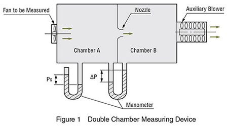
Holy crap, manometers are expensive AND most are not made for fan testing, especially at low pressure (according to manufacturers I've asked), or else they require a special dual-chamber testing unit, which is massively expensive to buy.
cooling-fan-double-chamber-measuring-device.jpg


I'm sure LonGwin (yes, that's how THEY type it, which makes sense since it's a Chinese, not American, company) has something like that.


A simple water manometer, Yellow Jacket 78075 Water Manometer Made of a Durable Plastic , is $56!


So, given that I'm horribly short on space at this point, and I'm going to have a 33" long noise-dampening chamber on my table, I don't need another box on top of that, so I want to make my own water manometer. Can anyone tell me how or point me to the clearest possible instructions on how to make it cheaply with plastic (cuz I'll definitely break it if it's glass)?


Thank yoU!
 

Paperdoc

Polypheme
Ambassador
You're going to a lot of effort to measure a small air pressure difference. Not clear why? But anyway, here's a hint.

The hardest part of such a device is reading the position of the water surface accurately - you're trying to read to +/- 0.05 mm or smaller! A commercial unit will be built with the water tube mounted at a very shallow ANGLE, not vertical, on a horizontal backing plate. Thus a real vertical column height of 4 mm can be spread over a long angled length of tubing of perhaps 100 mm (about 4") or more. Then you have to make your own measuring scale along that sloped tube, from 0 mm to 4 mm (or whatever the real vertical height is). And of course you MUST mount the system so that the base IS truly horizontal and the real vertical difference from bottom to top IS 4 mm or whatever your scale says.
 
  • Like
Reactions: ReveurGAM

Paperdoc

Polypheme
Ambassador
Yep, that's a classic manometer used to measure the DIFFERENCE between pressures on two sides. On this example, one side is open to atmosphere, and the other side is the "measuring"side so you're measuring how different that side is from normal atmosphere.

With this unit arranged with vertical tubes you can measure pressure differences of cm easily. But try to use that to measure a difference of 2.00 mm, and be confident that your result is NOT 2.10. (Don't forget, you READ TWO measurements - one from each side - and calculate the difference.

For a simpler unit you can use a J-shaped tube with a larger-diameter reservoir bottle attached to the short arm of the J. That bottle contains water and must have a tightly-sealed lid with a connection spout to connect to the pressure you are measuring. You set it up with nothing as the "input" on that connection tube, and mark the "Zero" pressure point where the water level is in the tall J part of the tube. Then you connect the pressure to be measured to the input connector and watch the tall tube level rise. Again you are measuring the DIFFERENCE in level of the water in the larger reservoir bottle and the tall measuring tube. But if you make sure the reservoir bottle is quite wide, that level will be almost the same for small pressure rises in the measuring tube.

But that still leaves the problem of reading that height accurately when it is small. Computer fans have a "pressure" rating which really is the MAX pressure that the fan can blow against - any higher backpressure resistance results in NO air flow at all. Those numbers can range from 0.5mm water to 4 or 5 mm water for VERY powerful fans. Most "pressure fans" suited for use on radiators have ratings of 2 to 3 mm water. Since you want to compare fans and conditions, you want to be able to read that value to a precision of at least +/- 0.1 mm - that is 1/25th of an inch!

So, as I said, for very low pressures like this one uses a different arrangement in which the "tall measuring tube" part of the system is almost horizontal and long, and the water level in the reservoir with no pressure applied is at the low end of that tube - mark that as the zero point. It is very handy if you can adjust water in the reservoir to match that zero point as you start. Then you measure a spot near the high end of the tube and find its REAL elevation (height above the low end Zero mark). From there you can draw a measuring "ruler" with even markings from 0 to 4 cm (IF your chosen high spot is exactly 4.00 cm above the zero point). If the distance along the sloped tube is actually 20 cm (200 mm, or 7.9 in) between real zero and real 4 mm, your custom scale will have magnified the precision of reading by a factor of 50. So along the custom scale you marked, 1.00 mm will represent 0.02mm of actual water column height difference.

NOTE in using such a device that the mounting method for the sloped back support plate for the tube MUST be set truly horizontal. For this is is best to have a small spirit level unit firmly fastened to the support plate and a way to adjust unit tilt slightly. Then ALL your work - including marking the initial Zero and high-pressure points and the resulting custom scale - MUST be done with the unit level.
 
Last edited:
  • Like
Reactions: ReveurGAM

ReveurGAM

Prominent
Sep 28, 2022
389
21
695
Thank you so much for the response! Very helpful!

A few things:
Again you are measuring the DIFFERENCE in level of the water in the larger reservoir bottle and the tall measuring tube.
The video says the sum, not the difference...?
For a simpler unit you can use a J-shaped tube with a larger-diameter reservoir bottle attached to the short arm of the J.
Please link to a video or instructions.
With this unit arranged with vertical tubes you can measure pressure differences of cm easily. But try to use that to measure a difference of 2.00 mm, and be confident that your result is NOT 2.10. (Don't forget, you READ TWO measurements - one from each side - and calculate the difference.
That's an excellent point so, ideally, I should not mark the tube but, instead, have the gradation on the backboard and make sure the tube is perfectly straight. I'm guessing that using hot glue might not work depending on the tube's material, so maybe epoxy? What do you suggest so that the measurements aren't obstructed?
Then you connect the pressure to be measured to the input connector and watch the tall tube level rise.
Ok, so I see that the fan I'm testing would need to be extracting air from the tube. How can I connect a fan (various sizes, although I can't see myself testing smaller than 80mm or larger than 210mm at this time) to a water manometer? Please link to video and/or instructions.
Those numbers can range from 0.5mm water to 4 or 5 mm water for VERY powerful fans.
The EK Furious Meltemi (discontinued) is 7.13, and I have another (forgot which) that is 11. Then there are server fans... ;)

So, as I said, for very low pressures like this one uses a different arrangement in which the "tall measuring tube" part of the system is almost horizontal and long, and the water level in the reservoir with no pressure applied is at the low end of that tube - mark that as the zero point.
That's an excellent clarification of what you wrote in your previous message - I was wondering if you meant almost horizontal, which means I need to make sure that I can store it vertically.
It is very handy if you can adjust water in the reservoir to match that zero point as you start.
What if I put a stopper in the open end when not in use? It seems like filling the reservoir could be achieved by having a stopper in it, too...?
From there you can draw a measuring "ruler" with even markings from 0 to 4 cm (IF your chosen high spot is exactly 4.00 cm above the zero point). If the distance along the sloped tube is actually 20 cm (200 mm, or 7.9 in) between real zero and real 4 mm, your custom scale will have magnified the precision of reading by a factor of 50. So along the custom scale you marked, 1.00 mm will represent 0.02mm of actual water column height difference.
Please link to a visualization of this, preferably a comparative one to help me understand.
NOTE in using such a device that the mounting method for the sloped back support plate for the tube MUST be set truly horizontal. For this is is best to have a small spirit level unit firmly fastened to the support plate and a way to adjust unit tilt slightly. Then ALL your work - including marking the initial Zero and high-pressure points and the resulting custom scale - MUST be done with the unit level.
By "unit level", are you referring to a "level" used to make sure something is perfectly flat?

Thanks again! You rock!
 

Paperdoc

Polypheme
Ambassador
1. The video says "SUM" because you are adding a positive reading (the upper level tube) to a negative reading (the drop of the lower level tube). That's the same as the DIFFERENCE between a positive and a negative number when you use the + and - signs: Diff = +x - (-x) = 2x. BUT in a system I described where the level in the wide reservoir is very nearly constant and you read only the one tube, you effectively use (-0) as the second measurement and ignore it. BUT this means you MUST ensure that the reading on the measurement tube IS zero when no pressure is applied.
2. I have no video. I can only try to describe the design.
3. Yes, epoxy to fasten the tube to the support board straight might work well. And marking the board, or even making a separate measurement label strip and attaching it to the board.
4. The fan does not pull air from the device. You set up your fan in a measurement chamber, and ensure that chamber has a small connection port. Ten you connect a simple tube from that port to the input connector of the reservoir. Whatever pressure is inside the chamber it transmitted to the manometer. Air is not actually flowing through this connecting tube.
5. If you need to measure very high pressures of 10 mm or more, you can adjust your manometer design. Either make it with a VERY long nearly-horizontal tube, OR use a shorter tube like 200 mm but mount it at a less shallow angle so the high end is 10 mm (or more) above the low end. The you make your measurement labels to suit.
6. The whole point of "adjust the water level" is to ensure that, with NO pressure applied, the manometer reading IS Zero.
7. The numbers I used were a simple example of how the readings can be more precise with this design. The central point is this. You establish two points along the measuring tube. One is the Zero pressure point. The other is a point near the upper end that you MEASURE accurately to be a known height (say, 4.00 mm, or whatever) above the zero level. The you work out how to mark off lines between those two to make readings easy.
8. The manometer works only IF you ensure that the VERTICAL difference between the Zero and high readings IS exactly what you set up above in item 7 (for example, 4.00 mm). The handiest way to do that is to be sure the long horizontal mounting board (with tube securely fastened at a shallow angle) is level at all times, beginning when you initially chose the high-end mark for the real vertical height difference.
 
  • Like
Reactions: ReveurGAM

ReveurGAM

Prominent
Sep 28, 2022
389
21
695
1. The video says "SUM" because you are adding a positive reading (the upper level tube) to a negative reading (the drop of the lower level tube). That's the same as the DIFFERENCE between a positive and a negative number when you use the + and - signs: Diff = +x - (-x) = 2x. BUT in a system I described where the level in the wide reservoir is very nearly constant and you read only the one tube, you effectively use (-0) as the second measurement and ignore it. BUT this means you MUST ensure that the reading on the measurement tube IS zero when no pressure is applied.
2. I have no video. I can only try to describe the design.
3. Yes, epoxy to fasten the tube to the support board straight might work well. And marking the board, or even making a separate measurement label strip and attaching it to the board.
4. The fan does not pull air from the device. You set up your fan in a measurement chamber, and ensure that chamber has a small connection port. Ten you connect a simple tube from that port to the input connector of the reservoir. Whatever pressure is inside the chamber it transmitted to the manometer. Air is not actually flowing through this connecting tube.
5. If you need to measure very high pressures of 10 mm or more, you can adjust your manometer design. Either make it with a VERY long nearly-horizontal tube, OR use a shorter tube like 200 mm but mount it at a less shallow angle so the high end is 10 mm (or more) above the low end. The you make your measurement labels to suit.
6. The whole point of "adjust the water level" is to ensure that, with NO pressure applied, the manometer reading IS Zero.
7. The numbers I used were a simple example of how the readings can be more precise with this design. The central point is this. You establish two points along the measuring tube. One is the Zero pressure point. The other is a point near the upper end that you MEASURE accurately to be a known height (say, 4.00 mm, or whatever) above the zero level. The you work out how to mark off lines between those two to make readings easy.
8. The manometer works only IF you ensure that the VERTICAL difference between the Zero and high readings IS exactly what you set up above in item 7 (for example, 4.00 mm). The handiest way to do that is to be sure the long horizontal mounting board (with tube securely fastened at a shallow angle) is level at all times, beginning when you initially chose the high-end mark for the real vertical height difference.
Thanks! I need to digest this...