Since there is no readable user guide for your UEFI, i can not look up from where the right settings for manual memory timings would be. Only way is when you boot into UEFI and navigate there.
You can do pics of your UEFI submenus and upload images here, just like i did when i showcased my UEFI to you.
But you can easily test out if both keys work the same or not.
Just open up any folder, where folder is active window. Then press leftmost ALT + F4 to close the window. Then same with rightmost ALT + F4. If one of the two doesn't work as it is supposed to, then you know which of the two keys doesn't work as ALT as default.
But that "cmd" lettering sounds like "command line", which would indicate running the command of "cmd.exe", which brings up Windows terminal.
you said "years ago", plural, so that must be at least 2 years ago, you shouldnt endure kaput functionality for that long, unless the stuff is discontinued technology or very expensive.
Thing is, i already have new KB at hand, but i haven't bothered to unbox it (Corsair K100 RGB with OPX optical switches), since it means i have to uninstall my iCUE version 4.0 software, mess around some more with it, so that i can install iCUE version 5.0. That, and i have to redo all my lighting profiles and macros and special key binds that my peripherals have. Oh, have to set my headset custom equalizer too. And for that tedious task, i haven't bothered to switch out my KB as of yet.
Better to do it clean. Old OS drive from another PC has plethora of issues when you try to make the OS bootable in new PC. IF the OS even boots that is.
At 02:05 in this video, it is showcased how to take off the backplate of the MoBo.
And in 06:35, it is showcased on how to take off I/O cover, so that you could get your hands to CMOS battery;
On 15:00 minute mark, the CMOS battery is seen that is connected to MoBo.
Got a response in MSI official forums and my fears were confirmed:
Replacing CMOS battery is as tedious as replacing wi-fi module, since there is no other way to access the CMOS battery, other than;
* removing MoBo from PC case
* removing MoBo backplate
* removing MoBo back I/O cover
And only then, you can get access to the connector and CMOS battery, which is glued to the back side of 3.5mm audio jack housing, using double-sided tape.
Better view of CMOS battery is seen at 30:55 and minute forwards from it, in the video i linked above.
Saving grace is that CMOS batteries last a long time. A decade or so. So, one shouldn't be worried about replacing the CMOS battery.
Since there is no readable user guide for your UEFI, i can not look up from where the right settings for manual memory timings would be. Only way is when you boot into UEFI and navigate there.
I am planning to print that out, and then to study the print, as its a bit of a challenge to study onscreen.
only just got the ancient Adobe Acrobat X Pro functioning again, by trying to update variously, without luck, then next session, an update option appeared, and after that it functions.
But you can easily test out if both keys work the same or not.
Just open up any folder, where folder is active window. Then press leftmost ALT + F4 to close the window. Then same with rightmost ALT + F4. If one of the two doesn't work as it is supposed to, then you know which of the two keys doesn't work as ALT as default.
But that "cmd" lettering sounds like "command line", which would indicate running the command of "cmd.exe", which brings up Windows terminal.
Thing is, i already have new KB at hand, but i haven't bothered to unbox it (Corsair K100 RGB with OPX optical switches), since it means i have to uninstall my iCUE version 4.0 software, mess around some more with it, so that i can install iCUE version 5.0. That, and i have to redo all my lighting profiles and macros and special key binds that my peripherals have. Oh, have to set my headset custom equalizer too. And for that tedious task, i haven't bothered to switch out my KB as of yet.
you should be able to use both keyboards at the same time, eg I have both the cheap Lidl USB cable keyboard and the upmarket wireless logitech. I can enter keys with both, eg use alt-f4 with the lidl.
also a bit weird: if I press caps lock on the wireless, the capslock led lights up on the lidl. the lidl one has a blue led 1 if you press numlock, and a blue led A if you press capslock including capslock on the other keyboard!
similarly you can use 2 mice at the same time, eg I sometimes have a USB cabled mouse and a wireless mouse at the same time.
so the thing to try is:
1. do a sector backup of the system drive, in case things go wrong.
you can do this with linux Mint, if via say gparted or Disks or even "df -h", you find the Linux name for your drive for that boot session, dont rely on that name being the same for the next boot session.
eg say it is /dev/sda and via the explorer find the name of a partition, eg say a partition is called xyz, it might be /media/mint/xyz/
the way Linux works, is the drive is say /dev/sda but the partitions on that are /dev/sda1 /dev/sda2 /dev/sda3 etc,
the M.2 drives use a slightly different notation, where this is something like /dev/nvme0n1 and I think the partitions of this are something like /dev/nvme0n1p1 /dev/nvme0n1p2 .... I'd have to reboot to Linux to be sure.
but you will see both namings in a partition editor such as gparted.
best to keep the entire source drive unmounted, that guarantees it doesnt change whilst being copied, ie you get a coherent copy.
if you dont access a drive which isnt the current system's drive, it shouldnt change, which needs presence of mind. so eg to ensure the Linux drive doesnt change, I go via the "try without installing" version of Linux.
determine these names each session you plan to do things, dont reuse them across sessions, as the drives could get enumerated differently.
on Ubuntu 8.10, these names might be say /dev/sda and /media/xyz/
you can read them off from gparted and the file explorer respectively, where with file explorer, the partition name is at the top of the window. its possible gparted has been discontinued, but it is available on the "use without installing" disk.
then if the drive is /dev/sda and the partition xyz is /media/mint/xyz/
reinstating in one step from a compressed copy might not work, instead you may need to decompress first, then copy the decompressed file.
decompressing can be done with gzip, find command line info via
gzip --help

OR for more extensive info:

man gzip

which should work with Google also, to get eg:

[URL]https://www.gnu.org/software/gzip/manual/gzip.html[/URL]
test whether it works on a small example, before decompressing a huge file. I mostly compress not decompress, so am not 100% sure of the decompress command. it is probably:
where -d is for decompress, -c means output to standard output, -k means keep the original files. because Unix is from an era when disks were small, you can decompress in place, where the original file vanishes and you get the decompressed file. but nowadays people prefer original files to be unchanged, and eg with optical disks this is the only option.
I have to boot to Linux to check the decompression command.
2. connect the new keyboard at the same time as the old keyboard, dont install the new keyboard, to see if it works with the old keyboards earlier version of the software. if it does, you could just use it with that old version of the software.
3. now install the new software WITHOUT uninstalling the old software, with any luck it will preserve all the configuration settings.
but do step 2 first of all, because if step 3 fails, you now know you can revert via step 4 to step 2. whereas if step 2 failed, you will have to do step 4 and abandon ship.
4. if everything goes wrong, reinstate the old system drive from the compressed copy by booting to Linux.
edit: you could of course just use restore points! set up a restore point, noting the date and time, then connect the new keyboard in addition to the old one, without installing anything, see if it works.
then install the new drivers and software.
see if it preserves the old config.
then if necessary shut down the computer. remove the new keyboard, reboot and revert to the earlier restore point.
Better to do it clean. Old OS drive from another PC has plethora of issues when you try to make the OS bootable in new PC. IF the OS even boots that is.
At 02:05 in this video, it is showcased how to take off the backplate of the MoBo.
And in 06:35, it is showcased on how to take off I/O cover, so that you could get your hands to CMOS battery;
On 15:00 minute mark, the CMOS battery is seen that is connected to MoBo.
Got a response in MSI official forums and my fears were confirmed:
Replacing CMOS battery is as tedious as replacing wi-fi module, since there is no other way to access the CMOS battery, other than;
* removing MoBo from PC case
* removing MoBo backplate
* removing MoBo back I/O cover
some of the back of the mobo is directly accessible without removing it, but not any screws!
this is where I think Gigabyte mobos are better than MSI variously, with Gigabyte you can access the battery directly just like that. eg I changed the one for the 2006 PC the other day.
although Gigabyte may use "bait and switch" (show one thing, supply another) with their review mobos, I think the mobos themselves are good design. to test them objectively you'd need to purchase the mobo as an end user and not test the boosted ones they send to reviewers.
MSI have put the battery on a cord, which is a good idea, but then put the battery in a nuclear bunker a mile below ground!
they ought to make it accessible from the back panel without even opening the PC case!
And only then, you can get access to the connector and CMOS battery, which is glued to the back side of 3.5mm audio jack housing, using double-sided tape.
the video is tricky to decipher for this, but I wonder if there is a way to sneak to the battery without removing the heatsink?
you dont need to unplug the battery cable, just to get to the battery capsule. could the mobo back panel be removed without removing the heatsinks etc?
the double sided tape also sounds dubious, they dont expect people to trek to town to buy some new tape when changing batteries?
I really liked my Fujitsu-Siemens laptop, because with that you could change the hard disk and memory without voiding the warranty.
it had 2 zones, the one users could access, and the other which had a warranty seal.
MSI is a bit like these new smartphones and laptops where you cant access the batteries, and when the battery runs out you have to junk the machine.
You need to view UEFI in Advanced mode, then OC Menu - Advanced DRAM configuration. And under there is listed the tCL, tRCD, tRP, tRAS etc, that you can manually configure.
I do not have enough table real estate to put two KB's next to each other. That, and i'll run out of USB ports on back I/O panel, since each KB has 2x USB connections (one for KB, another for USB passthrough, where i tend to connect the mice).
But yes, i do know that i can use 2x KBs at once. This is what i do when i take out and use PS/2 KB, to access UEFI.
this is where I think Gigabyte mobos are better than MSI variously, with Gigabyte you can access the battery directly just like that. eg I changed the one for the 2006 PC the other day.
It is not that Gigabyte is better and MSI is worse. Instead it is about the era when the MoBos were made.
For example;
My high-end MSI Z97 Gaming MoBo, made 2014, has CMOS battery in easy to reach spot, between 2nd and 3rd PCI-E x16 slot:
Same goes with my high-end MSI Z170A Gaming M5 MoBo, made 2015, whereby CMOS battery is also in the easy to reach spot, between 1st and 2nd PCI-E x16 slot:
But if i were to take modern Gigabyte MoBo, e.g X670E Aorus Master (E-ATX), can you see the CMOS battery there:
I had to look up from Gigabyte X670E Aorus Master manual where the CMOS battery is, and it is under the chipset heatsink.
Whereby it isn't any different to reach CMOS battery as it is in your MSI MoBo. It is actually worse, since:
* need to remove MoBo from PC case
* need to remove MoBo backplate
* need to remove M.2 cover that covers 3x M.2 slots (between PCI-E x16 slots)
* need to remove chipset heatsink
So, it is not the brand issue, but instead era issue, where MoBo manufacturers doesn't consider replacing CMOS battery as common occurrence, more like one in a million.
It is not only MSI, but EVERYBODY. Every MoBo manufacturer who makes MoBos. And this is more of an issue with high-end MoBos, where MoBos are filled with loads of stuff, resulting the placement of CMOS battery in obnoxious place.
For example, low-end MSI X670E Tomahawk Wifi MoBo has CMOS battery in easy to reach place, bottom-left corner of the MoBo:
With this, it would be easy to create proprietary connection battery, whereby when battery is toast in few years (few years because planned obsolescence), you have to buy same brand certified battery again with the proprietary connection, IF you want to use your PC at all.
Not worth it for end users. But it would be good revenue source for MoBo manufacturers.
Also, nothing would then stop MoBo manufacturers to use different connector on each different chipset and after, say, 5 years, discontinue producing the battery. So that after the battery is toast (like i said, lifetime 2 years), and you want to buy new battery, MoBo brand says: "We do not make this battery anymore. If you want to use the PC, buy a brand new MoBo.". So, tough luck. Whereby you need to scrap perfectly working MoBo, but without working li-ion CMOS battery, MoBo won't boot.
I'd rather have the CR2032 battery, which is universal, than some proprietary, short lifespan junk, which MoBo manufacturers would force me to use and only buy it from them.
I will probably try to install a 2nd win 10 later tonight.
I have taken screenshots of the mobo hardware settings, via the F12 key, which takes a .bmp screenshot, to the selected drive, to the top level, to FAT or FAT32 only. thus looks like the mobo has an implementation of a basic subset of FAT. I think FAT was designed to enable easy basic access to the filesystem, probably just to the top level of the filesystem. the mobo doesnt allow directory navigating, nor filename setting, you just select a drive, and it decides a name which isnt in use already.
I worked down the options for each screenshot, not always screenshotting the final set of options. with each screenshot there is a path to that screen in the image. I havent changed image format from .bmp to say .jpeg or .png, as there are 36 screenshots. it appears to select the first unused name, in the order given here:
You need to view UEFI in Advanced mode, then OC Menu - Advanced DRAM configuration. And under there is listed the tCL, tRCD, tRP, tRAS etc, that you can manually configure.
you dont need to, you just put the original out of reach on the cable, and only bring it in reach if you need it. the idea here is just to have both temporarily to see if the new one works with the earlier settings. if it does, you can junk the old keyboard.
but if it doesnt work, you temporarily need the old one to shut down the system, then to disconnect the new one.
That, and i'll run out of USB ports on back I/O panel, since each KB has 2x USB connections (one for KB, another for USB passthrough, where i tend to connect the mice).
you can daisychain the new keyboard to the old one then! and daisychain the mouse to the new one then boot up the machine, and see what happens. before all that to create a restore point and note the time, because otherwise you wont know which restore point!
which is the story of the leprechaun and the red scarf. where the leprechaun tied a red scarf around the tree near where the gold was buried, and promised to not remove the scarf. when the guy returned he found the leprechaun had put scarves around every tree in the forest and couldnt locate the gold.
if it all works, then you power down, attach the new keyboard directly, detach and junk the old keyboard, because kaput stuff generally has negative monetary value: you'll have to pay someone to remove it! people sometimes try to sell kaput stuff on ebay, you generally cant.
and now you do the 2nd experiment, which is to install the new software.
doesnt the old software have some "export settings" and "import settings"?
earlier era wireless uses rechargeable AAA batteries, which dont last long, and its a nuisance removing and recharging those.
but if you study the products available, some nowadays have lithium ion charging via a USB C cable, where you can use the mouse or keyboard whilst it is charging as the supplied cable is 1.3m with the one I have here.
the lithium ion charge for the handshake mouse literally lasts months. the keyboard charge runs out faster. both have a sleep function, so if not used they power down.
eg the MX Vertical mouse is 100% even though I recharged it ages ago, whereas the MX Keys S is 45%, where I recharged it some days ago.
you need to power each off if you arent using them, eg when you power down the computer, the mouse lasts much longer if you do that. in the early days I'd leave it permanently powered on, and it still lasted weeks.
advantage is its a keyboard or mouse like any other, but no cable. so no clutter and you can carry the keyboard around the room and use it.
So, it is not the brand issue, but instead era issue, where MoBo manufacturers doesn't consider replacing CMOS battery as common occurrence, more like one in a million.
It is not only MSI, but EVERYBODY. Every MoBo manufacturer who makes MoBos. And this is more of an issue with high-end MoBos, where MoBos are filled with loads of stuff, resulting the placement of CMOS battery in obnoxious place.
I disagree, they can just create a new standardised battery, it just needs to supply 3V as before, its not a difficult problem.
it would be foolish to design a new battery for every mobo, or for every manufacturer.
as the clock architecture goes way back in time, and I think was designed by Motorola, as it doesnt change with time, the battery doesnt need to change with time. they can create a standardised lithium ion battery compatible with the old watch batteries.
this is what I find idiotic about smartphones, where each one has a different battery. this makes it much riskier and more expensive to manufacture the batteries.
there arent many mobo manufacturers, and many seem to be taiwanese, eg Gigabyte and MSI are taiwanese, it wont be difficult for them to agree a new standard.
whereby when battery is toast in few years (few years because planned obsolescence), you have to buy same brand certified battery again with the proprietary connection, IF you want to use your PC at all.
you are presuming they will use a proprietory battery, but you then argue that it will be futile if they do this, and concluded that they musntnt use a lithium ion battery. but this is an incorrect conclusion, from the argument, all you have argued is that they mustnt use a proprietory battery not that they mustnt use lithium ion.
its like saying if you are a millionaire you have to live in a mansion, but then you need lots of servants to maintain the mansion, therefore no point being a millionaire. but in fact you could be a millionaire who lives in a normal house!
if my mouse and keyboard and torch can use lithium ion, I think its not a big problem for a mobo to.
everything should be standardised unless there is a compelling argument not to, this is basic basic, and was known even in the 1800s. eg the existing battery format is standard with the CR2032, and the mobo size is standard, the sockets eg SATA, USB etc are standard, as are the power sockets etc.
I cant believe that in this ocean of standardisation anyone would even consider a proprietory format for something as basic as a battery!
Not worth it for end users. But it would be good revenue source for MoBo manufacturers.
Also, nothing would then stop MoBo manufacturers to use different connector on each different chipset and after, say, 5 years, discontinue producing the battery.
So that after the battery is toast (like i said, lifetime 2 years), and you want to buy new battery, MoBo brand says: "We do not make this battery anymore. If you want to use the PC, buy a brand new MoBo.". So, tough luck. Whereby you need to scrap perfectly working MoBo, but without working li-ion CMOS battery, MoBo won't boot.
I'd rather have the CR2032 battery, which is universal, than some proprietary, short lifespan junk, which MoBo manufacturers would force me to use and only buy it from them.
and I would rather have a 3V standardised lithium ion battery, I find it ridiculous that lithium ion batteries havent been standardised, where everyone has to reinvent the same worn out wheel until it disintegrates from over-reinvention.
I decided to install 64 bit Windows 10, but couldnt find the BDR install disk, so decided to burn another. couldnt find the iso, so had to download this first, which took a thousand years. next problem, to burn it to bluray, the old bluray software doesnt work on this machine. time to install the free software which came with the QL bluray writer.
did that, then burnt the 64 bit Windows 10 install bluray. of course they then offer me an upgrade, for $39, which looked interesting, eg with software for editting HD videos for bluray, decided to opt in, but then they gave 2 freebies, one of 996MB and the other 421MB, and the upgrade itself 227MB.
the documentation URL didnt work, so a customer service ticket to Cyberlink.
decided best to download right away otherwise I will forget as the idea will get snowed under endless other stuff. the best way to remember to do things, is to do them right away then nothing to remember!
each download took ages to download.
then decided best to install the graphics card next, the RTX 4060.
for this there is a snag that for the PCIe clip to click, the Be Quiet! cooler is in the way to be sure of that. I pressed the 4060 and it made a clicking sound, so I just hope it is attached properly.
the supplied 4060 manual is incoherent and a load of rubbish. eg it doesnt mention that the 4060 plug has a rubber covering. couldnt see the gold leads, so guessed it was a covering, pulled it and it removed. this photo shows a green arrow from the covering to the plug:
I think it is disgraceful that they sell these products at extortionate prices, and then are too lazy to create manuals for the specific product, and also that they cant be bothered to do photos and instead have these pathetic diagrams in the so called manuals.
next problem is the stupid quickstart shows a 4x2 and a 3x2 socket, but in fact there is just a 4x2, I dont know if there is anything else to connect, there is a strange red widget at the top, marked by a green ? in this photo: http://www.directemails.info/tom/graphics_card/graphics_power.jpg
I then had to remove the PSU plate, to connect up a 4x2 to the 4x2 in the photo. the 4x2's on the PSU inaccessible, because a jungle of earlier cables, so rejigged those starting at the lowest row, furthest away first. this way I can see what is leftover. originally they began at the top row.
with this I got the 4060's 4x2 attached to the PSU, and at the 4060, looked at the shapes of the individual pin sockets to orientate the plug.
the mobo manual is a bit confusing suggesting the uppermost PCIe covers of the tower back panel need to be removed, but in fact it was the 2nd and 3rd ones. no idea what the point of the first one is, other than to confuse people.
got the PSU cover plate back on and screwed in with 3 thumbscrews at the right side of the tower.
and now a new problem, the graphics card just has 3 DP sockets and 1 HDMI socket, each with a dummy shielding it from dust:
and so all the high quality video cables I bought are frustrated!
I spent a lot of money on those cables, but all are a waste of time for the graphics card!
as all are USB3 C or are HDMI extenders, or are USB3 C to HDMI, or USB3 C to DP,
but what I need is a DP to DP cable. Geforce evidently dont like the USB3 C socket for graphics.
the only HDMI cables I have around are from a bygone era, and probably not fast enough. I'd rather just go directly to DP.
any advice on a long eg 5m DP to DP cable? which will deal not just with this graphics card + monitor, but maybe with even faster hardware? that way in the future, I wont have to junk the cable.
the graphics card box appears to say 8K 60Hz.
also any advice on longer male to male HDMI cables that would deal with the monitor and graphics card's data rates. I probably prefer to use DP because of the bad experience of HDMI via mobo graphics, where it is blurry. but I might buy an HDMI to HDMI cable to compare with the DP to DP, to see if that blurriness is a mobo thing or a monitor thing.
I have some memory of Aeacus saying HDMI to HDMI can be done via optical cables.
so at the moment the graphics card is installed, but is unutilised as it doesnt have a USB3 C socket, and instead I am using the mobo graphics via the USB C socket at the mobo back panel.
my guess is that if you use the USB C socket of the mobo back panel, that that goes via the mobo and not via the 4060.
I emailed MSI about why not put the battery at the back panel, as there is unused space there. then you can change the battery without even opening the tower case. they said they will forward the idea!
eg it doesnt mention that the 4060 plug has a rubber covering. couldnt see the gold leads, so guessed it was a covering, pulled it and it removed. this photo shows a green arrow from the covering to the plug:
No need to mess with that one, since it is either fan or LED (or both combined) port. It is marked red so that when you remove GPU heatsink (some people do that), you know where the slot is located, so you can unplug the fans wire.
any advice on a long eg 5m DP to DP cable? which will deal not just with this graphics card + monitor, but maybe with even faster hardware? that way in the future, I wont have to junk the cable.
Most modern GPUs come with PCI-E slot cover, so that the PCI-E pins won't get damaged.
No need to mess with that one, since it is either fan or LED (or both combined) port. It is marked red so that when you remove GPU heatsink (some people do that), you know where the slot is located, so you can unplug the fans wire.
so right now, the graphics card is installed, but I wont be able to use the new graphics till Monday when the cable will arrive. wont have much time Monday, so it will be Tuesday. will try to do the permanent install of Windows 10 64 bit then.
but meanwhile I will try to do the 2nd temporary installs of Windows 10 + 11, and probably a 2nd install of Linux, just to see how each deals with the multi OS boot.
probably will put Windows 10 on a different M.2 from Windows 11 like 35Below0 suggested ages ago. and Linux Mint on one of those 2 as it boots directly.
The power socket on MoBo, where CPU power plugs in, is also 4 pins in a row, in two rows. Do you call that socket as 4x2 as well?
Or how about the main ATX power socket on MoBo, are you calling it 12x2?
If you use the logic of "pins per row times how many rows there are", then what socket is 18x2? Or 82x2?
Thing is, you can not reinvent and slap your own names onto hardware, since no-one would understand what you'd be talking about. It is better that you use the official naming, known by everyone.
The initial images in the beginning of MoBo manual are universal and doesn't apply strictly to your MoBo or your setup.
E.g GPU in MoBo manual is shown as dual-slot and using 6-pin PCI-E, while GPUs that actually meet that, are quite few.
Then, PC case shown has power button dead smack in the middle of front panel, where intake fans are. And of course, bottom mounted PSU. Not all PC cases have bottom mounted PSU. Those general installation steps should be taken as guidelines, rather than actual rule.
And to expand on what Aeacus wrote, since we're talking power supply things here, giving things your own names rather than using standardized ones increases the risk you make a catastrophic mistake.
The power socket on MoBo, where CPU power plugs in, is also 4 pins in a row, in two rows. Do you call that socket as 4x2 as well?
Or how about the main ATX power socket on MoBo, are you calling it 12x2?
And to expand on what Aeacus wrote, since we're talking power supply things here, giving things your own names rather than using standardized ones increases the risk you make a catastrophic mistake.
there isnt any danger, because each pin of the PSU cable plug is a different shape, so there is only one way to do things, which is the correct way, taking into account the detachment lever also. ie it is idiot proof design, idiot proof combined with my mxn scheme is perfect.
and this is generally true of PC cables of today, there is only one way to connect which is the correct way. where there is some confusion is the different forms of USB C or USB A, eg only some USB C sockets work for video. and with that the jargon is unmemorable and confusing, where they are moving to what I said a long time ago which is shape + speed rather than confusing version numbers.
with one of the PSU cables, the shapes of the pin plugs didnt match, then eventually I saw that the cable at one end said PSU and at the other end something else, and the PSU end fitted perfectly at the PSU.
so my naming scheme is super efficient, whereas the official one is complicated to remember, and doesnt actually help. if I use that here, it will only help you, it wont help me or help any beginners, its just a load of jargon clutter for the experts to talk over the heads of the beginners!
using my scheme I'll connect up much faster than someone using the official scheme, eg with the GPU, I could see it was a 4x2, then looking in the bags of Seasonic PSU cables, I found a 4x2, checked the pin shapes, wasnt right, then saw it said PSU, so checked the other end, correct, and bingo perfect fit.
you tell me an example where my scheme will be wrong?
ie where an mxn cable will fit the wrong mxn socket with the individual pin plug shapes matching?
eg 2x2 is potentially ambiguous variously, but in fact only one way to connect it, the detachment lever also needs to align.
I only use this notation for the approx square shaped PSU pin plugs, and not for say the fan plugs and sockets and eg VGA and PS2 sockets.
I can and I do all the time, it is called evolution of language.
in maths, progress often comes from clever reinvention of terminology. standardisation is only good if it is efficient, when it is inefficient it is an encumberance, eg USB 3.2 Gen 2x2, that is bad terminology. better to just call it USB C 20Gbps if that isnt ambiguous. our maths faculty put a lot of energy in standardising terminology for all their courses, but books from other countries often slap on their own terminology.
the ability to reinvent better terminology is central to progress, otherwise you can get tangled up in bad terminology. eg "AI" is bad terminology, as it encompasses totally incomparable things such as chatbots and generative AI, which arent the same stuff. generative AI is fiction, whereas chatbots are regurgitation.
and eg where I said USB terminology should be based on the speed rather than the version, you then supplied an article saying there is a move to just this, so I am ahead of the curve!
I disagree, unofficial naming often eclipses official naming,
and in any case its not known by everyone, only by hardware zealots.
eg Brexit is unofficial terminology, even you use that. most people dont even know what the official terminology is! if France leaves the EU that will be Frexit, and obama's healthcare policies were called obamacare, and Thatcher's agenda was called thatcherism, eg fight the trade unions and privatise, Reagan's agenda was reaganomics, the russian imitation of Concorde was called concordski, the Boeing 747 is called a jumbo jet. the channel tunnel is called the chunnel (the train tunnel under the ocean between London and Paris). the charity people with clipboards who accost you for money in city centres are called chuggers, a contraction of charity and mugger.
the british conservative party refer to the british civil service as the blob!
you often use the 12,34 notation where with the english language you should only use the 12.34 notation, with the german language you should use 12,34
you could give someone very wrong advice by using the wrong notation!
eg you said "M2_1 - PCI-E 5.0 x4 = 15,75 GB/s", but in the anglophone world, that means 1575 GB/s. the only clue for us is that usually comma is only used to group 3 digits at a time, not 2. but you are allowed to group 2.
in Britain, the US, and every anglophone country on earth you write eg 1,234,567.89 but in Germany and evidently in Estonia you write 1.234.567,89
if you ever program, and you use your notation the program will either fail or you will get a syntax error! I think with the internet your notation will eventually become obsolete.
if you right select properties for a Windows file or drive, you will get the notation I mention eg:
our notation is because "," is just for visual tidiness, whereas "." demarcates the end of something, same as with written language even in Germany. and in spoken english we say eg the square root of two is one point four one four two ....
the "." of numbers in english is called the decimal point not the decimal comma!
the numerical notation is part of the language, you can get into financial jeopardy if you use the wrong notation for the language. and in fact they didnt even teach us this when I learnt german at school in England, and it seems they didnt teach you this in your english classes at school. I only learnt this when communicating financial matters with an accountancy firm in Germany, where they sent me crazy numbers!
The initial images in the beginning of MoBo manual are universal and doesn't apply strictly to your MoBo or your setup.
E.g GPU in MoBo manual is shown as dual-slot and using 6-pin PCI-E, while GPUs that actually meet that, are quite few.
Then, PC case shown has power button dead smack in the middle of front panel, where intake fans are. And of course, bottom mounted PSU. Not all PC cases have bottom mounted PSU. Those general installation steps should be taken as guidelines, rather than actual rule.
this is where they ought to give photos, because a genuine photo is always reality,
I emailed a second email to MSI giving a list of suggestions, including that they should use photos for their manual, eg their diagram and info on removing the screwless frozr heat sink cover plate of the M2_1 is very confusing. I told them to shunt the CPU towards the top of the tower, to create space on the other side of the graphics card, and to put some of the mobo in vertical planes like with a PCI card, to free up space for sockets. the arrangement of circuitry on circuitboards is all automatically done via software, where the engineers design the schematics, but the software rejigs this to the mobo. timing could be a problem if things are too far apart, but they have to experiment a bit to get a rearrangement that works.
I told them also that the 90 degree SATA cable plug is stupid, why did they supply one, and why did they only supply 4 SATA cables when the mobo has 6 SATA sockets, and that the side entry SATA sockets are inconvenient, that my 2010 Gigabyte mobo has the SATA sockets pointing upwards, far superior arrangement where you can parachute to any socket. I literally have to connect SATA cables to this mobo blind, guessing as a jungle of cables in that area and I cannot do this from above the mobo because too many cables.
I told them also to use a cover plate for the CMOS battery zone that can be removed from above, eg with screws, or magnetic like the Be Quiet! lid, or screwless like their M2_1 lid. or to have the CMOS battery accessible from the back panel without needing to open the PC case.
they can do all these things, the only reason they havent, is they havent thought of such.
yes, but he was the only specific suggester of this that I was 100% sure of, because his recommendation was so emphatic! I wasnt 100% sure who the other suggesters were, without having to trawl through the discussion!
so my naming scheme is super efficient, whereas the official one is complicated to remember, and doesnt actually help. if I use that here, it will only help you, it wont help me or help any beginners, its just a load of jargon clutter for the experts to talk over the heads of the beginners!
using my scheme I'll connect up much faster than someone using the official scheme, eg with the GPU, I could see it was a 4x2, then looking in the bags of Seasonic PSU cables, I found a 4x2, checked the pin shapes, wasnt right, then saw it said PSU, so checked the other end, correct, and bingo perfect fit.
Except we see it happen a ton around here with disastrous results; the shapes aren't that different. It's extremely presumptive for someone who has helped zero people with their PCs while most of the regulars have literally helped thousands of people resolve thousands of problem to claim their inexact, oddball terminology for a safety part is obviously superior.
the guy didnt acknowledge whether the tip helped, so I cannot say for sure that I helped him, but his next post was that things were now working.
with the above, sometimes when nothing is happening, in fact something is happening, but you have to wait ages, maybe even hours before concluding that nothing is happening.
It is bad business to call two completely different purpose power sockets by the same name, without any indication to tell the diff between the two.
PCI-E 8-pin and EPS12V 8-pin can not be called 4x2 based on the pins and rows.
There have been plenty of people who have plugged PCI-E power cable into EPS12V socket or EPS12V 8-pin into GPU PCI-E 8-pin socket. And end results have never been pretty.
PCI-E 8-pin and EPS12V 8-pin ARE NOT interchangeable. One CAN NOT call these two sockets by the same name just because it is convenient for them.
Or this cable, which by your logic, is 4x1, at both ends:
While in fact, both connectors on either end are completely different. You can not call them both 4x1. Left one is FDD power connector and right one is MOLEX connector.
See, even your logic fails, since you have 0 clue what connectors i'm talking about, when i use your "superior naming scheme". And i can tell you, that you've used 82x2 for years. Heck even your new AMD PC has 82x2 connectors.
82x2 is the pin layout of PCI-E x16 slot (18x2 is pin layout of PCI-E x1 slot).
You know the naming of PCI-E slots and you have 0 issues saying PCI-E x16. Yet, you don't call PCI-E x16 slot as 82x2. So, better to drop calling slots by the pin layout and instead use the name given to them, that everyone knows, including you. It's far easier to learn the naming, rather than trying to memorize pin layouts of every socket you come across, without being able to tell a diff if you're talking about e.g FDD power of MOLEX power.
Also, how your logic would cope with this power socket:
It has two rows of 6 pins and 3rd row has 4 pins. Can't call it 6x2 nor 6x3. So, what your logic says?
Took me some time to figure out what you were talking about.
This reminds me our argument where you called every single memory module as SIMM, even the DDR DIMM. Not only that, you even called the SIM card inside the mobile phones as SIMM as well.
You are capable of learning the correct naming of hardware, rather than reinventing the wheel and giving them all your own custom name. So, why be stubborn about it?
Most people know the PSU power connectors by the correct name because everybody; PSU brands, retail stores, tech forums - they all use the same terminology.
If you do not know the correct naming of something, no worries, we can tell you what the correct name is. So next time, you know what this connector is named as.
Prime example is from your another topic, where you asked:
Richard1234 said:
my Gigabyte motherboard from 2010 has the following socket labelled FDD on the motherboard:
very tricky to photograph, by chance that photo came out right, further ones totally blurry! the "FDD" label is just about visible, and has a blue arrow pointing at it. I dont know what you'd call that socket?
there isnt any danger, because each pin of the PSU cable plug is a different shape so there is only one way to do things, which is the correct way, taking into account the detachment lever also.
Many 1st time builders doesn't realize how much force is needed to plug in the power cables into power sockets. I've seen countless of cases of people brute-forcing PCI-E 8-pin into EPS12V 8-pin, since after all "both are 4x2 sockets". And learning the hard way later on, what they did wrong.
Heck, even i had to brute force power connection into power socket, by bypassing the keyed design, since there was no other way.
With my old AMD build, my old PSU: Seasonic S12II-520 80+ Bronze, only had one EPS12V 8-pin power connector to power the CPU. But MoBo only had EPS12V 4-pin power socket and capacitor just next to it.
Top left image: EPS12V 8-pin cable is correctly aligned to the EPS12V 4-pin power socket, but since capacitor is in the way, i can not plug the connector in.
Top middle image: Even when moving the connector one pin column over, i can't plug it in, since capacitor is still in the way.
Top right image: Only when i move the connector half-way over, i have enough space to plug the connector in. But this means the plastic key is incorrect. Whereby only way to get it in, is brute forcing it in.
Bottom left image: And this is what i had to do, since there were no other way.
Bottom right image: Only after i upgraded my PSU to Seasonic Focus+ 550 80+ Platinum and bought CableMod custom sleeved power cables, i was able to use correct keyed EPS12V 4-pin power cable inside the EPS12V 4-pin socket.
This trick is only for people who know what they are doing. I know the pinout of EPS12V and there was no harm, for me to brute forcing it into "wrong" place, by bypassing the keyed design. This is not something i suggest for novice builders.
and this is generally true of PC cables of today, there is only one way to connect which is the correct way. where there is some confusion is the different forms of USB C or USB A, eg only some USB C sockets work for video. and with that the jargon is unmemorable and confusing, where they are moving to what I said a long time ago which is shape + speed rather than confusing version numbers.
Your high-end PSU has the luxury of power cables being clearly marked by what end goes where. But not all PSU power cables are marked with lettering, to make sense which end goes where. This is especially true with cheaper PSUs.
CPU socket itself can't be moved towards the top since else-ways, there will be severe restrictions on what CPU coolers can be used. Instead, to give GPU more space, it can be solved by making 1st PCI-E slot as x1 and 2nd PCI-E slot as x16, like it has on my MoBo. This gives more room between CPU air cooler and GPU.
Daughter boards are thing in the past. But in a sense, GPU is also a daughter board, since it extends the circuitry of a MoBo.
If one needs more sockets than common consumer ATX (or E-ATX) MoBo is able to provide, then one should look towards server rack MoBos instead. Those have far more space for all kinds of slots.
E.g this quad-CPU 6U server rack MoBo with plethora of sockets:
first a progress report, that I have installed a 2nd Windows 10, and thereby learnt various new ideas. I also learnt that my camera's autofocus cannot handle Windows blue screens, its unable to focus! if there is some variation of colour eg text then it can.
I probably will install all the OSes on the same drive, which is what I originally wanted to do.
I took photos of each step, then forgot to take the photo of one, and there was no back button at the next step. so rebooted and began the install again.
I installed the 2nd Windows 10 at the far end of the 2T M.2 drive, in exactly 260Gig, set as 260 x 1024 MB. doing this by creating a new partition of size remaining space minus 260 x 1024MB, then creating a further partition in the remaining 260 Gig, then deleting the previous partition as the installer only allows creation in the leftmost zone of any unused space. thus you need tricks to have a different left point.
now when I booted the new OS, I am greeted by this screen:
now when I changed the default to Windows 11, and then choose that option, it reboots to that without alternative options.
but if I power down, and switch off the mains, and then reboot, now Windows 11 is the default one, with the other 2 options, and on selecting the new default, it goes directly without reboot.
so this means on the Windows side, I can get the machine to boot directly to any installation of Windows 10 and 11 _________________________ (A)
The next experiment will be to install a 2nd Windows 11, so the comment here is if you install Windows 10 last. Will see if true also if 11.
I prefer to not assume anything, as Windows sometimes worsens with later versions.
Now, what about Linux Mint 21.1?
I installed everything via the Windows 10 64 bit bluray, via the external optical QL writer drive set as the boot drive. I noticed that Windows 10 was booting directly, the install had changed the UEFI boot order!
anyway, dabbling with the UEFI, I changed the boot option to the Ubuntu option mentioned earlier. And it booted correctly to Linux Mint.
so in addition to (A) above, I can also boot directly to Linux Mint.
thus I can reconfigure the machine to boot to any OS on the drive, hence I intend now to reinstall all OSes to the same drive, and probably also install some smaller scratch installs of all OSes to experiment with.
reconfiguring the Windows side back to the new Windows 10 install as the default option, I then booted Linux Mint, and selected its first Windows boot option, and it continued to the new Windows 10 install.
the Linux Mint windows boot option thus continues to whatever you have configured for Windows. will need to verify this if Windows 11 is the last install.
the only thing I forgot to check is to reconfigure to the first Windows 10 OS as default.
with the new 2nd Win 10, I installed the mobo drivers, in order to access the internet, and imported the bookmarks and merged history and also passwords to Firefox, not done this yet for MS Edge.
noting whenever I could remember how much disk space was used.
the initial Windows 10 install used some 127 Gigabytes, after installing the mobo drivers, some 130 Gigabytes used.
and I am writing this message from the new 2nd Win 10 install, logging in to Tom's hardware using the saved passwords, just to check everything's working alright.
this one is a 6x2, just looking at the grid of squares part,
the 4 extra pins make the totality sufficiently unique that visually there will be no confusion.
the big confusion is mostly with the power sockets and plugs, other things mostly just require labels, eg the FAN labels for the fan plugs.
eg with SATA there is only 1 kind of plug for data, and one for power, both of which are L shaped.
confusion occurs when you have too many similar things going on, eg all the different USB A sockets. USB C versus USB A no confusion because they look totally different. my Microsoft USB cable mouse doesnt work with the 3rd party USB panel's USB3 and USB2 sockets! the Lidly USB cabled keyboard does work with the USB3 socket.
for this specific example, I wouldnt use terminology, I'd just use a photo, a photo is worth a thousand words and a hundred diagrams!
you do need common sense and some sensible protocols with my scheme!
Took me some time to figure out what you were talking about.
This reminds me our argument where you called every single memory module as SIMM, even the DDR DIMM. Not only that, you even called the SIM card inside the mobile phones as SIMM as well.
the problem isnt mine, but is with the people creating the terminology, as SIM and SIMM are pronounced the same.
good terminology is a skill, it should be easy to remember and sound different from existing terminology, examples are eg laser, and bluray. no confusion at all.
big firms will pay market researchers to decide what terminology is good, where they will test the terminology on volunteers.
You are capable of learning the correct naming of hardware, rather than reinventing the wheel and giving them all your own custom name. So, why be stubborn about it?
Many 1st time builders doesn't realize how much force is needed to plug in the power cables into power sockets. I've seen countless of cases of people brute-forcing PCI-E 8-pin into EPS12V 8-pin, since after all "both are 4x2 sockets". And learning the hard way later on, what they did wrong.
you must never apply force with sockets unless you are really sure, eg I think the Molex requires force. a socket which requires force is a badly designed socket.
you should use a latch of some form if you want the connector to hold, eg a lever release with the better SATA plugs.
people who apply force are people who grew up in the 1980s and earlier, when things were badly designed!
with my 2007 monitor, it has a superb DVI socket, which has 2 reinforcing screws, you get a rock solid connection. better than HDMI where sometimes the plug starts to slip!
some of the Amiga cables had 2 reinforcing screws.
Heck, even i had to brute force power connection into power socket, by bypassing the keyed design, since there was no other way.
With my old AMD build, my old PSU: Seasonic S12II-520 80+ Bronze, only had one EPS12V 8-pin power connector to power the CPU. But MoBo only had EPS12V 4-pin power socket and capacitor just next to it.
Top left image: EPS12V 8-pin cable is correctly aligned to the EPS12V 4-pin power socket, but since capacitor is in the way, i can not plug the connector in.
Top middle image: Even when moving the connector one pin column over, i can't plug it in, since capacitor is still in the way.
Top right image: Only when i move the connector half-way over, i have enough space to plug the connector in. But this means the plastic key is incorrect. Whereby only way to get it in, is brute forcing it in.
Bottom left image: And this is what i had to do, since there were no other way.
Bottom right image: Only after i upgraded my PSU to Seasonic Focus+ 550 80+ Platinum and bought CableMod custom sleeved power cables, i was able to use correct keyed EPS12V 4-pin power cable inside the EPS12V 4-pin socket.
This trick is only for people who know what they are doing. I know the pinout of EPS12V and there was no harm, for me to brute forcing it into "wrong" place, by bypassing the keyed design. This is not something i suggest for novice builders.
when things are designed correctly, there is only one way to do things, which is the correct way, and you should never use force.
with the above hack that you are doing, the designers should have seen that their socket needed something that isnt available, and should have supplied a converter socket, where at the one side is your 4x2 and at the other is the 2x2.
there is a saying that a good workman doesnt blame his tools, I have my own saying, that a good manufacturer shouldnt blame his customers, instead customers should blame the manufacturer if its problematic to use their manufacturings.
nowadays you have Trust Pilot and amazon reviews etc, where you can blitz bad design!
the moment you do any betatesting, it becomes obvious that a design is bad, and what should be done instead.
all these problems are because of incompetence of manufacturers.
things are manufactured to be used, so you need to test a prototype to see if it is usable, without a lot of hassle. what they do is as stupid as designing a house without a door, where you have to enter the house down the chimney!
Your high-end PSU has the luxury of power cables being clearly marked by what end goes where. But not all PSU power cables are marked with lettering, to make sense which end goes where. This is especially true with cheaper PSUs.
and this is a problem of design rather than luxury, because it doesnt cost anything to put labels.
it shows that the cheaper ones havent been betatested properly, a lot of the top end stuff also hasnt been betatested properly. these problems would be detected and remedied very soon if they did even a small amount of betatesting.
with my 2006 and 2010 PCs, the PSU had integral cables, where you only had to attach the far end!
now the 2 sided cables are a good idea, as you only install the ones you will use. but anything where there is risk of damage by the consumer, needs to be idiot proof.
there are some financial websites, which involve danger, and you cannot use the website until you correctly answer a questionairre! to ensure you know the dangers. rather than a "click here that you have read the warnings".
Instead, to give GPU more space, it can be solved by making 1st PCI-E slot as x1 and 2nd PCI-E slot as x16, like it has on my MoBo. This gives more room between CPU air cooler and GPU.
not everything of the past is bad! and the GPU is a very powerful component at 90 degrees.
hardware components communicate via buses, and can be at any angle at all relative to the bus.
there is collective amnesia, where ongoingly civilisation forgets useful things, often replacing them with worse things. and it pays to study a past era, eg I have a book written just before WW2 started, where the guy talks of current affairs of that time, and it is crazy the stuff he says. the book was published in September 1939, and the guy has no idea a big war will start!
a lot of things which are done, are simply because people hadnt thought of other ways of doing them, and also because society has forgotten many things.
if you go back to say the 1920s and earlier, people were inventing and discovering much more radical things than today. Today its mainly about making things faster and smaller. eg CD to DVD to bluray, to quad layer.
the reason is the way discovery was organised was quite different and much better than today. where there were much more big leaps of progress, today it is just lots of small leaps. eg CD to bluray, is about going from a red laser to a blue laser, blue is higher frequency than red, enabling much more data.
my suggestion is just to free up space on the mobo, to allow better access to sockets. but as you suggested, setting the graphics card lower down would enable access to the graphics card latch. currently I cant access it as the Be Quiet! is in the way. I will need to remove the Be Quiet! in order to remove the graphics card.
also the tower door should be much easier to open, currently I have to undo 2 screws, someone should invent handles and latches!
the core technology is very advanced, but the way it is put together is a dog's breakfast.
creating this screenshot on Win10, I can see the Win10 screenshotting is much easier to use, with Win11, I have to go to a submenu to snapshot the entire screen. with win10 I can select that directly. unfortunately I cannot screenshot the screenshot options! would need a camera!
this does mean that you can compare the machine with graphics card versus without graphics card AFTER the graphics card is installed!
by using a cable to the mobo backpanel USB C video port to see the machine without graphics card, and then the cable to the graphics card for the graphics card version.
I am going to collect the DP to DP and HDMI to HDMI cables after this message, but I probably wont have time to utilise them till tomorrow.
when the cable says 16K at 60Hz, what does the 16K refer to?
is that 16K as in Ultra HD being 4K?
I dont understand that notation, because
HD = 1280 x 720
2K = 2560 x 2440,
and this is 2x the HD dimensions,
but 4K = 3840 x 2160 which is 3x the HD dimensions, and is thus 9x as many pixels.
I dont know how they got 4?
also what about different bit widths per pixel or component?
if you reduce this, you can send more pixels at the same data rate.
I think some things are 10 bits per component, although I think 8 bits per component is easier for software, as software can easily access each component. with 10 bits, software has to shift and mask which will slow things.
it needs to be either 8 bits per component, or 16 bits, or 32 bits, other amounts will cause normal software to be slower. the graphics card might have hardware to do other bit-widths directly, but at the CPU side it will be slower. the CPU can only access 8 bits, 16 bits, 32 bits and 64 bits in hardware. possibly there are some extensions of the CPU that can deal with 128 bits, I didnt study that. 8 bits per component with a 4th unused byte, means 32 bits per pixel, which enables both RGB components and the entire pixel to be accessed in one CPU instruction. for data rates to the monitor the extra byte would be slower, but that can probably be junked before the data is sent to the monitor.
one other thing, I emailed MSI technical support, that the mobo often doesnt boot properly, and they said to download the latest 7D69v1E BIOS from the MSI website, and use the M-Flash function to update it.
to then clear the CMOs, to enter BIOS and press F6 to load optimized defaults, then press F10 to save and reset to test again.
I wont try that just yet, and will need to carefully study about reflashing the BIOS so I dont make any mistakes!
The correct term for what they measure in cd/m2 is Luminance not brightness. Brightness historically refers to the light's perceived intensity at any given point of the source called candela or in the past candelpower. Nowadays brightness largely refers to the quantity of light or the perceived power, the lumen is the photometric analogue of the radiometric watt. So 300cd/m2 means if you stand at the center of the highly diffused 2D surface, the dead center will hit you with 300candela, and this will drop in proportion to the cosine of the angle between the center (surface normal) and the actual screen surface. This assumes a perfect diffused surface.
In recent times memory effect in Li-Ion has taken on a new meaning. One study showed that it has a small effect, but this is just one study and there needs to be more to get a better picture of the situation as that study didn't translate well to realife and left unanswered questions. Nowadays in the lithium community the big question is "how much of what seems like ordinary natural capacity fade is actually the result of some certain detrimental charging practices, particularly regards to voltages?"
There are those who fuss about it and still loose capacity, and those who don't treat their batteries well and don't loose capacity.
Memory effects are well known to users of nickel-cadmium and nickel-metal-hydride batteries. If these batteries are recharged repeatedly after being only partially discharged, they gradually lose usable capacity owing to a reduced working voltage. Lithium-ion batteries, in contrast, are considered to have no memory effect.
However, slight voltage change can lead to substantial miscalculations in estimating the state of charge of batteries.
To feel anything, voltage should be 50V or more for AC and 70-110V or more for DC.
This is incorrect.
There is no memory effect in NiCd in the everyday. It only happens in very rare types of large format cells and requires precise charging to happen, so its so unlikely to be seen by any ordinary folk.
Further, NiMh doesn't suffer from the memory effect.
What both do suffer from is what is known as voltage suppression or lazy voltage. This is from repeated similar cycling and results in the voltage sagging during discharge giving the impression of heavily discharge cell and as a result some electronics can shut off thinking the cell is almost empty. The problem is made alot worse by the fact that the cold can really make the voltage seem lower.
EDIT: To mitigate this effect, you frequently (every ~20cycles???) discharge the cells right down to just below ~1V, then charge them at a fairly high c-rate, repeat a few times. But it's not an exact science
A slight voltage change in Li-ion wont cause any kind of miscalculations if the measuring device is well made and setup (you input its actual measured capacity). Like a quality battery monitor allows. However after many hundreds of cycles with li-ion, the voltage does change a little, its more a concern for lifepo4 with its flat curve, it can lead to the charger finishing early.
Finally, saying you need 50VAC to feel something is potentially dangerous, impedance is the gate keeper of current flow and under many situations (soft skin, wet skin. firm grip, etc) you can feel something at alot lower voltages. Of course this leaves out the most crucial part that which is the path of current flow through the body.
Battery memory effect is umbrella term to describe several different effects. Namely an effect observed in NiCd rechargeable batteries that causes them to hold less charge. It describes the situation in which NiCd batteries gradually lose their maximum energy capacity if they are repeatedly recharged after being only partially discharged. The battery appears to "remember" the smaller capacity.
I have a device that has NiCd rechargeable battery in it and over the ~5years of me using it once a week, it's battery capacity has dropped off the cliff. Used to when i got 3-4 uses out of it before battery was empty. Now, i can only get maybe half of use out of it, if it even powers on, that is. And i can't replace the battery since it's built-in. I have to buy completely new device.
Other devices i have with Li-Ion rechargeable battery, have lasted for far longer, with little, if any drop in charge over the years. So, NiCd is clearly inferior and has fundamental flaws to it.
Finally, saying you need 50VAC to feel something is potentially dangerous, impedance is the gate keeper of current flow and under many situations (soft skin, wet skin. firm grip, etc) you can feel something at alot lower voltages. Of course this leaves out the most crucial part that which is the path of current flow through the body.
What voltage can a human feel?
Answer and Explanation: If the finger is having sufficient sweat that it can be able to detect 12 V alternating current very quickly. With the proper prevention taken, and with dry human fingers can able to feel 50 V alternating current and 70 V to 110 V direct current.
progress report: I did get the monitor cables, and decided to print out the instructions for flashing memory, because I cannot use the computer whilst doing this! But I remembered the printer overruns the edges using the inbuilt generic Windows drivers. so decided to install the printer drivers from the CD or DVD of the printer, and this then was a quagmire, where it decided to flash a firmware update for the printer and I ran out of time.
tomorrow Tuesday I will work on flashing the memory, and installing the 2nd Windows 11, the 2nd Linux Mint 21.1, and perhaps get to install the permanent installs of Windows 10 and 11, probably to the other M.2 drive, where I will leave these temporary installs in place until those have stabilised.
reconfiguring the fans is straightforward, as with each what I do is 0 volts up to 65 centigrade, and then linear up to max voltage at 75 centigrade. and this has resulted in the PC being virtually 100% silent most of the time. only sometimes powering the fans, except at the start. I dont mind that. what I dont like is perpetual fan noise.
right now I am writing this with the new 16K @ 60Hz DP to DP cable, and have also connected the optical HDMI to HDMI cable to the same monitor. it seems this graphics card doesnt have an installer disk. if I switch to the HDMI input for the monitor, it is dreadful, a bit blurry. where I booted up with DP. Now maybe if I boot up with HDMI input it will be better. but with HDMI currently, the desktop is bigger than the monitor, and I cant access the rest of the desktop, and various software loads a window beyond the monitor!
luckily if I switch input back to DP, then everything is good.
so far I dont see any improvement with the graphics, are there any impressive graphics demos I can try where the graphics card will outdo the mobo graphics impressively?
I accept that this is the official scheme, but its a slightly dubious naming scheme! because for 2560 to be 2K, that is round downwards to 2000, but for 3840 to be 4000, is round upwards or round to nearest. 2560 rounded to nearest or upwards would be 3000. the only logic I can see is round to nearest power of 2, ie 1K, 2K, 4K, 8K, 16K, 32K, 64K, .... which is a new concept! if this is the case, I dont know which is the boundary point between say 2K and 4K, will it be 2000 x squareroot(2)? = 2828.427125... ? where 2828 is 2K and 2829 is 4K?
keeping to powers of 2 is sensible, as that allows pixel perfect mapping to higher resolutions. when I say pixel perfect, I mean where the image is precise right up to a pixel, rather than some blur.
I am of the opinion that you need to keep to width = 2^m x 1920, height = 2^m x 1080 (A)
because anything else, and it can become impossible to rejig the graphics nicely, this is a problem with my 3000 x 2000 HP Laptop of 2023, and also with laptops where say the height is less than the above, where some buttons on some windows cannot be accessed, a real nuisance!
what I personally want is a laptop with a standard sized keyboard complete with numeric keypad, and then a screen conforming to (A) above. which of course does mean the keyboard will be a smaller depth from the screen height, but so be it! eg they could put a ginormous wrist rest in the unused space.
for me for capacities I prefer to talk in bytes, which includes prefixes such as kilo, Kilo, mega, Mega, giga etc eg gigabytes, and for data rates I prefer bytes/second, which includes all the above prefices also, eg kilobytes per second. I think eg MB means 1024 x 1024 bytes, whereas mB means 1000 x 1000 bytes, but people sometimes interchange these 2. I checked when arranging partitions for Windows 10 and 11, that 512 x 1024 MB emerges as a 512 GB partition rather than 524.288 (512 x 1024 = 524288).
probably the convention today is B = byte, and b = bit?
where Windows creates 2 further partitions automatically for the first GPT partition, I think those are deducted from the requested size.
with early home computers they talked of nybbles also, which are 4 bits, where nybble and byte are wordplays on nibble and bite. and Kilo is to approximate 10^3=1000 by 2^10=1024, where Kilo, Mega, Giga, is inspired by the metric system's prefices. some of my friends at school and uni dabbled with the early home computers and would talk of nybbles.
in the very early days also, some computers had 9 bit bytes, eventually they standardised bytes to 8 bits. the next size up is a word, there is confusion for this terminology, where 16 bits is either a word or a short word, and 32 bits is either a word or a long word. and then 64 bits, with GNU programming, this is generally a long long word.
USB means universal serial bus, now I dont know if by serial they mean it sends one bit at a time?
eg serial port versus parallel port of old era computers, I dont know if that serial port just sent 1 bit at a time, whereas the paraellel port sent bits in parallel on parallel wires?
which then might justify speeds given in bits per second, but the start and end of that journey is bytes, so the fact the transmission is bits is irrelevant, and it would be better to talk of bytes per second.
modern CPUs are optimised for handling bytes, 2 x byte, 4 x byte, and 8 x byte. aligned on 8 bit boundaries. unaligned ones and other widths can be used to reduce space usage, but this is slower. 8 bit boundary access of 1, 2, 4, 8 bytes can be done in one CPU instruction, ie very fast. where each 8 bit boundary has an address, counted 0, 1, 2, 3, 4, .... There is one thing of confusion, that say Motorola 68000 series, counts the bytes forwards: 0, 1, 2, 3, 4, ..... whereas Intel counts the bytes backwards: .... 4, 3, 2, 1, 0 which leads to subtle bugs. many programmers arent aware of this problem as they only program for the one architecture.
I only learnt of this problem with the computing degree, where it was a fundamental idea they taught us.
eg if the first long word in memory for Intel is $01234567, with Motorola it is $67452301. because Intel sees the bytes as .....,01, 23, 45, 67 whereas Motorola sees these as 67, 45, 23, 01, .....
badly written programs will crash when moved to the other architecture!
I think the PPC architecture allows both protocols with some low level configuration option. mathematically the Intel protocol is best.
if USB is 1 bit at a time, why? why not send say 8 or 16 or 32 bits etc in parallel? noone will stop you.
for me the video signal is a data rate, and would be bytes per second.
I dont like bits per second, because that is then 2 different schemes, where I cant compare like with like and one can misread Gbps as GBps, ie it is confusion prone. There are of course people out there who like and want confusion, to prevent people accomplishing things.
as a data rate, for me the video signal is not about pixel widths or heights, but is the amount of data. where its for the monitor to rejig the data, eg more pixels and less colours. I had approx 1997 a Microvitec multisynch monitor, with many different display options, eg all kinds of refresh rates, resolutions etc. where the limiting factor is how many bytes per second. I still have that monitor mothballed, huge item.
as regards the 16K, and 32K. I think 4K already is beyond what I can visually discern, eg my 3000 x 2000 13" HP laptop screen is beyond what my eyes can see, BUT I can see a usefulness of say 16K and 32K which is if you had really huge really high res screens.
eg say a wall size screen, where its as high res as say a 4K monitor. which would be super expensive of course, and eg for me I dont have the space, where all my walls are shelves and storage.
if it is too high, there is the problem that it wont fit through a door! you might have to remove a window and get it in that way! the other problem is it might be too heavy to lift!
In Britain in the last few years, digital billboards have begun appearing everywhere along the roads, which are ginormous, where its a bit like in the original Bladerunner film, but without audio, not the recent rubbish remake, but the pixels are relatively big. in supermarkets also they have large video screens promoting the nearby biscuits or other wares. if you go back to say 2018, the billboards were all paper based, where these guys would appear with ladders and buckets of glue and rolls of paper, and manually change the adverts! Today they just click a button in an office and all the billboards change. but sometimes the graphics goes kaput, and everyone can see the malfunction from far away!
It takes a while to download since it's relatively big.
For much smaller, but still good GPU benchmark, predecessor of Superposition can be used, known as Heaven,
link: https://benchmark.unigine.com/heaven
But for RTX 4060, i'd use Superposition, since it can take advantage of RTX series of GPUs. Heaven is far older, released in 2009.
To test the GPU, select a preset. For iGPU, i wouldn't use anything above 1080p preset, Medium quality. Maybe even 720p quality. For RTX 4060, highest i'd go would be 1440p preset. And while it can run 4K as well, FPS wouldn't be much, especially when quality is high.
But you can use Custom preset as well, defining quality aspects on your own.
E.g run 1080p Medium preset off the iGPU and write down the end results. You can even look at the benchmark during it's pass, to see how smooth it is.
Then run the same preset with RTX 4060 and look if you spot a difference. End results will be far better than with iGPU.
Telemetry is shown top-right corner when bench is running and summary at the end of the run.
Unigine Heaven - Custom 1080p preset
Taken way back, when i was running Win7 and GTX 1060 GPU:
Unigine Superposition - 1080p Medium preset
Win7 OS with my old GTX 1060 GPU.
Unigine Superposition - 1080p Medium preset
Win10 OS with my current GTX 1660 Ti GPU. Quite a ways better than my previous GTX 1060 GPU.
but its a slightly dubious naming scheme! because for 2560 to be 2K, that is round downwards to 2000, but for 3840 to be 4000, is round upwards or round to nearest. 2560 rounded to nearest or upwards would be 3000.
which then might justify speeds given in bits per second, but the start and end of that journey is bytes, so the fact the transmission is bits is irrelevant, and it would be better to talk of bytes per second.
Saying "bits per second" is bigger number than saying "bytes per second". And since for most people bigger number means better, mainly bits per second is used.
E.g SATA3 - 600 MB/s vs 4800 Mbps. Or 6 GB/s vs 48 Gbps.
Or my max download speed, which my ISP displays as: 500 Mbps but what in reality means 62.5 MB/s.
Serial communication is a term used to describe systems used for telecommunications, as well as certain technologies used for computing. When using serial communication, only one bit is transferred at a time, for example over a communication channel or computer bus. This is different to parallel communication, where several bits are sent at the same time. Many computer networks, as well as many lines where data is transferred over a long distance use serial communication.
Parallel connection requires dedicated wire for each data transfer and only one bit of data can occupy the wire at once. On shorter distances, parallel is faster but on longer distances, serial is better (less cost).
In a nutshell, difference between Serial and Parallel:
Well known Serial connections are: USB, Ethernet, SATA.
Well known Parallel connections are: PCI, PCI-E, PATA (IDE).
Here is also short, 2min video, explaining very well the differences of Serial and Parallel:
ok, I am downloading it just now, will install and do the tests later when the download has completed, Firefox says in 22 minutes.
I got quagmired where I decided to update Windows 10, and then couldnt access any folders. so had to reset, and will have to reinstall everything.
I also forgot to save the bookmark settings before resetting, but luckily I have those for 27th April. I found a neat trick for saving Firefox history, which is to import the history to MS Edge, and then save from there.
to get them back to another Firefox, you'd import history from MS Edge to Firefox, Firefox has no history export. there are 3rd party add ons, but I havent experimented with those. this is where its worth having a scratch install of Windows 10 and 11, to test whether things work.
and with all this, you'd need to say save the original history of MS Edge, then delete it, then import from Firefox, then save to file, then delete history, and then import the earlier saved version.
have got the printer reinstalled, and just now am printing out the BIOS manual, which is approx 100 pages.
the plan is to flash the memory as advised by MSI, I think they only want to give technical support for the latest BIOS, and thus are telling me to install that. I have it on the flash drive ready.
today is going to be a long day!
I emailed MSI about the clear CMOS button, whether the mains should be off, or if the mains on and the machine powered down, or other. no reply yet.
But for RTX 4060, i'd use Superposition, since it can take advantage of RTX series of GPUs. Heaven is far older, released in 2009.
To test the GPU, select a preset. For iGPU, i wouldn't use anything above 1080p preset, Medium quality. Maybe even 720p quality. For RTX 4060, highest i'd go would be 1440p preset. And while it can run 4K as well, FPS wouldn't be much, especially when quality is high.
But you can use Custom preset as well, defining quality aspects on your own.
E.g run 1080p Medium preset off the iGPU and write down the end results. You can even look at the benchmark during it's pass, to see how smooth it is.
Then run the same preset with RTX 4060 and look if you spot a difference. End results will be far better than with iGPU.
Telemetry is shown top-right corner when bench is running and summary at the end of the run.
Unigine Heaven - Custom 1080p preset
Taken way back, when i was running Win7 and GTX 1060 GPU:
Unigine Superposition - 1080p Medium preset
Win7 OS with my old GTX 1060 GPU.
Unigine Superposition - 1080p Medium preset
Win10 OS with my current GTX 1660 Ti GPU. Quite a ways better than my previous GTX 1060 GPU.
2560x1440 is sometimes referred as 2.5K as well. Though, i like to use 1440p when talking about it.
that would be more informative. what about where the screen isnt full height like with laptops? do you give the height, or what the height would be if full height?
E.g: 720p, 1080p, 1440p, 2160p (rarely used, instead most people know it as 4K), 8K, 16K etc.
2560x1440 is only used with PC monitors. There doesn't exist any TV that natively displays 1440p.
Yes.
Saying "bits per second" is bigger number than saying "bytes per second". And since for most people bigger number means better, mainly bits per second is used.
E.g SATA3 - 600 MB/s vs 4800 Mbps. Or 6 GB/s vs 48 Gbps.
Or my max download speed, which my ISP displays as: 500 Mbps but what in reality means 62.5 MB/s.
Parallel connection requires dedicated wire for each data transfer and only one bit of data can occupy the wire at once. On shorter distances, parallel is faster but on longer distances, serial is better (less cost).
that does answer one question I was going to ask, which is if SCSI is parallel, the answer is yes! which maybe explains why SCSI has fat cables!
that video is similar to our computing degree lectures on hardware, where they explained a lot of principles, but we didnt dabble with actual hardware.
with these things, you could engineer other methodologies than the ones officially known, and probably they do use other methodologies which arent documented.
you could hack bidirectional by having 2 unidirectional cables.


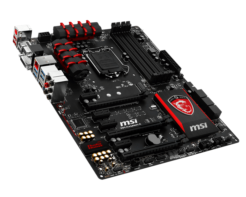
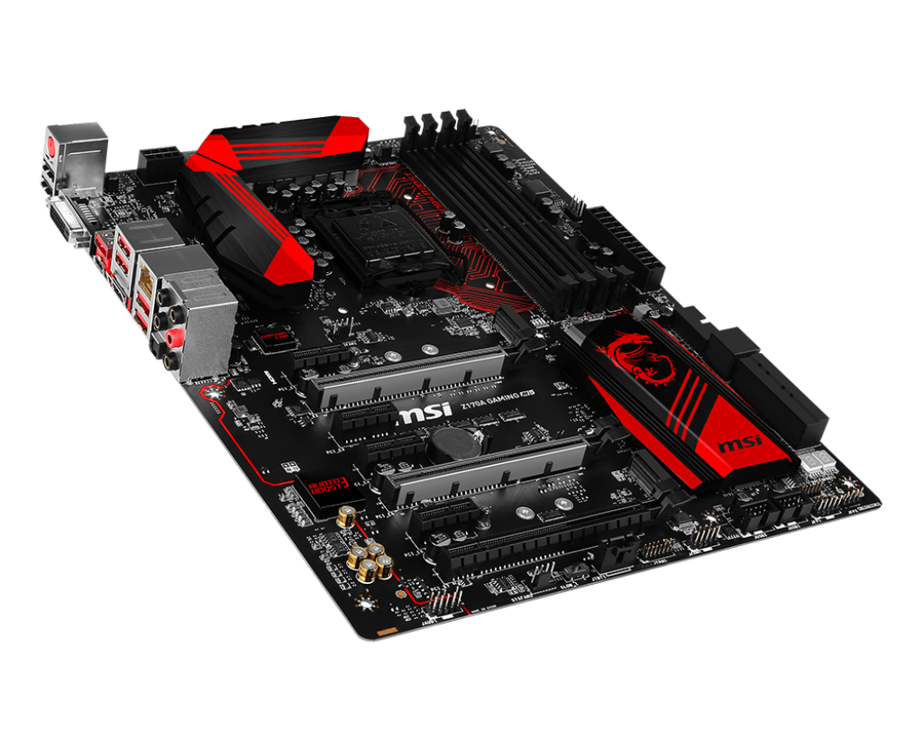
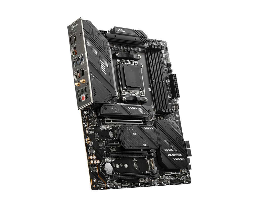


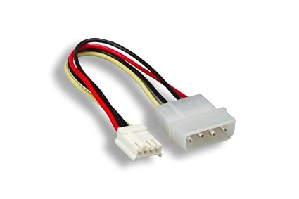
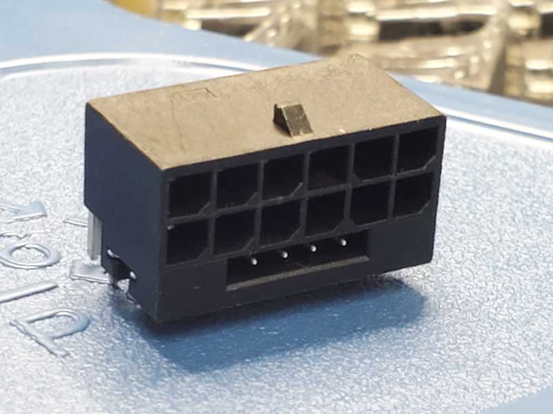

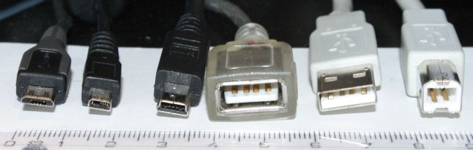
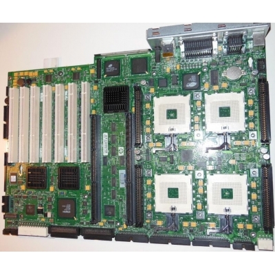


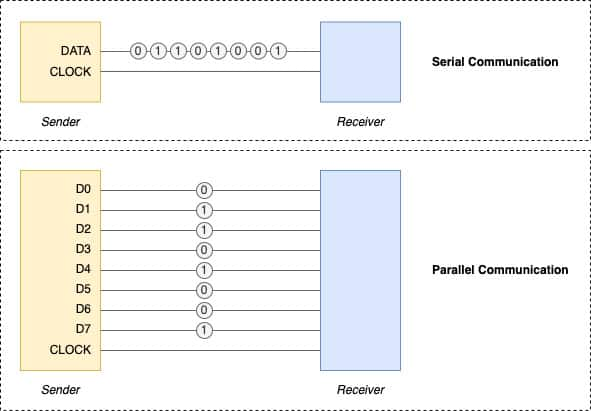
 Twitter